VAMP 140 Overcurrent and earth-fault relay
Technical description
VAMP Ltd
38
Vamp 24h support phone +358 (0)40 573 6316 VM140.EN011
4. Connections
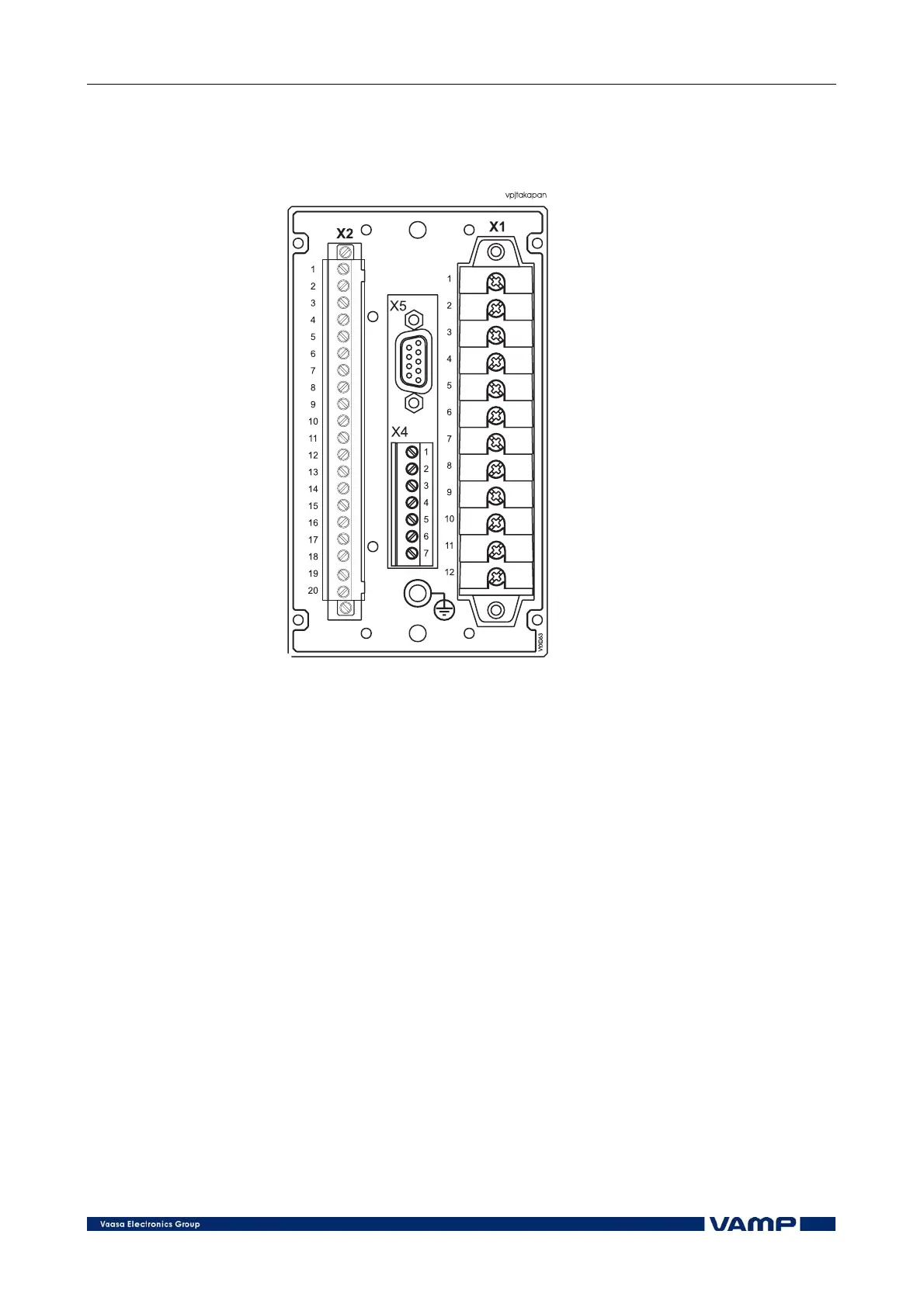
Figure 2.5.2-1 Connections on the rear panel of the VAMP 140 relay.
The VAMP 140 relay is connected to the protected object
through the following measuring and control connections:
• Phase currents IL1, IL2 and IL3 (terminals X1: 1-6)
• Residual current I0 (5 A input: terminals X1: 9-10, 1 A
input: terminals X1: 7-8)
4.1. Digital input
Further the relay can collect position information and alarm
signals via the digital input (terminals X2: 4-5) and store the
information in the event register.
The digital input can be used to:
• Block protection stages under certain conditions.
• Get time stamped event code from any auxiliary
contact.
• Control the output relays.
• Supervise the trip circuit.
Potential-free contacts for position indication must be available
in the protected application.