VANNER
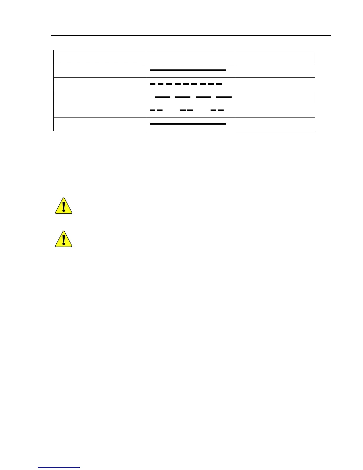
3.1.5 Power Status LED
LED Display and Color
Solid Green
Blinking Red Fast
Blinking Red Slowly
Blinking Red Intermittently
Solid Red
3.1.6
AC Output GFCI Duplex Receptacle
The AC output
neutral conductor is connected to
inverter.
This conforms to National Electrical Code requirements that separately derived AC sources
(such as inverter and generators) have their neutral condu
neutral conductor from the utility is tied to ground at the AC breaker panel.
Do not connect AC neutral to AC ground downstream of the GFCI. This would cause the GFCI to
trip.
Never connect the inverter output to
power.
The inverter would be destroyed
Series Inverter Owner’s Manual
Flash Pattern Status
DC O
AC Output GFCI Duplex Receptacle
neutral conductor is connected to
AC ground and inverter
This conforms to National Electrical Code requirements that separately derived AC sources
(such as inverter and generators) have their neutral condu
ctors tied to ground in the same way that the
neutral conductor from the utility is tied to ground at the AC breaker panel.
Do not connect AC neutral to AC ground downstream of the GFCI. This would cause the GFCI to
Never connect the inverter output to
another AC power source such as a generator or utility
The inverter would be destroyed
.
Series Inverter Owner’s Manual
- 7 -
ground inside the
This conforms to National Electrical Code requirements that separately derived AC sources
ctors tied to ground in the same way that the
Do not connect AC neutral to AC ground downstream of the GFCI. This would cause the GFCI to
another AC power source such as a generator or utility