VANNER
Incorporated
Owner’s Manual
300 Watt VLT Series Inverter Owner’s Manual - 8 -
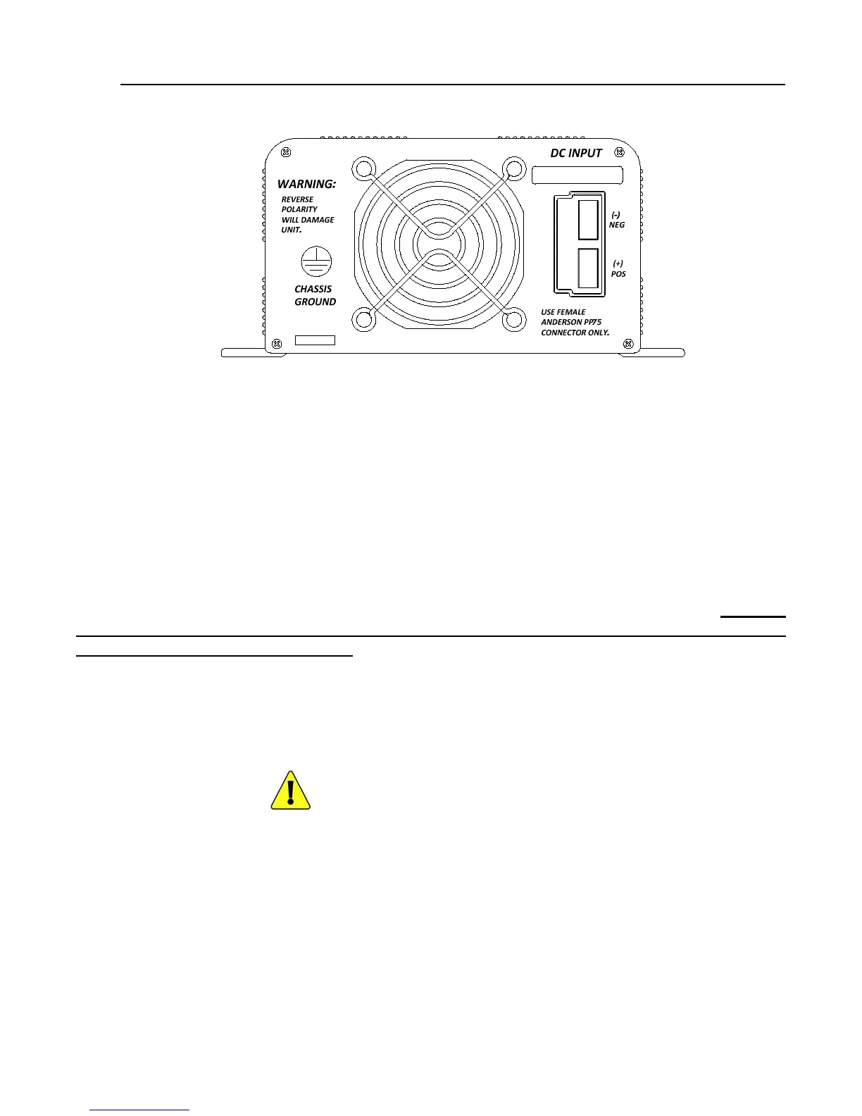
3.1.7 Rear Panel
3.1.8 Fan
Do not obstruct the rear fan exhaust or front ventilation intake openings. Allow at least 3 inches of clearance for
airflow.
3.1.9 DC Input Terminals
DC Input terminals are Anderson Power Claw for use with Anderson PP75 Powerpole Connectors. Included
separately are two Anderson #1300 DC Input Connectors with #5900 Contactors for use with 6 GA wire and
#5912 Bushings for use with 8GA wire.
Connect DC Input Terminals to a 12v battery (24v battery for 24v units). (+) is positive,(-) is negative.
Reverse
polarity connection will blow the internal fuses (cannot be replaced) and may cause
permanent damage to the inverter.
3.1.10 Chassis Ground Bonding Lug
Connect Chassis Ground Bonding Lug to vehicle chassis using 12AWG or larger copper wire.
WARNING!
Operating the inverter without a proper ground
connection may cause an electrical hazard.