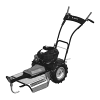
BDR-595D Adela
9
5 Instructions for use.
5.1 Assembling the machine.
Ask your dealer to provide unpackaging of the machine and briefing.
Grip points for unpackaging the machine from the container: In front on the cutting disk,
Rear on the U tube of the machine frame.
If you do the machine assembly yourself, follow the below instructions:
Note: Washer size (e.g. ∅8.4 mm) is at all times presented as a diameter of washer hole.
1. Take the machine out from the box and all parts from the packages.
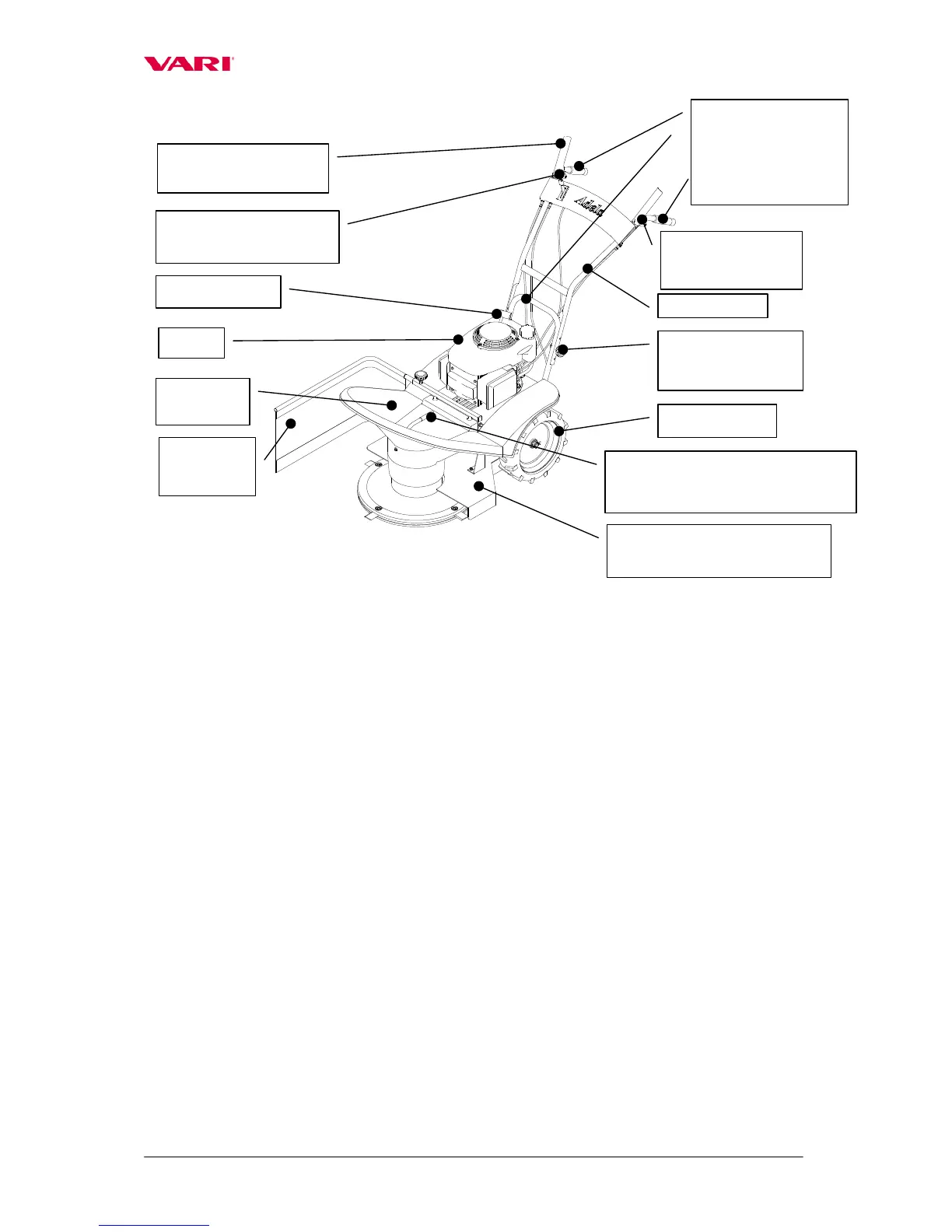
2. Turn the handlebars so that the handrails point to the rear of the machine.
3. Attach the handlebars (1) onto the frame by means of bolts with squares (2), washers Ø
8.4 mm (3) and plastic rosettes with internal tread (4) at a required height. Fix Bowdens
to the handrail by using plastic tightening tapes (5).
4. Put the upper casing (6) on the machine and screw it to the machine by using bolts
M6x20 (7) with large flat washers Ø 6.6 mm (8). Provide the bolt heads with plastic caps
(9).
5. Slide the handgrip (10) on the treaded part of the column (projecting from the upper
casing). Screw the handrail by using a self-locking nut M8 (11) with flat washer Ø8.4
mm (12). The nut M8 should be properly tightened! Provide the nut with a plactic cap
(13).
6. Bolt the upper casing (6) to the metal holder on the lower casing (14) by means of bolt
M5x10 (15) and a large flat washer Ø5.5 mm (16). Mudguards (17) are to be screwed to
the upper casing (6) by using bolts M6x16 (18), nuts M6 (19) and large flat washers Ø
6.6mm (20).
Travel wheels
Engine