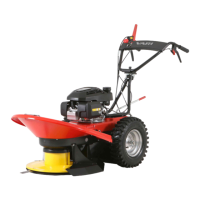
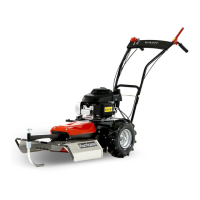
F-550
Engine Unit F-550 , F-550G F-550B F-550 INOX
Model - HONDA GCV190A N2G7
53
B&S 850Series
TM
122R02-0122-B1
54
HONDA GSV190A N2G7SD
55
Maximum engine RPMs (set) min
-1
3200 ± 100
Maximum engine incline / short-term
56
∠
20° / 30° 15° / 30° 20° / 30°
Fuel tank capacity l (liter) 0,91
57
1,13 0,91
58
Fuel gasoline oct.No. 91-95
59
Engine oil capacity l (liter) 0,55 0,59 0,55
Oil rating SAE / API SAE 30 or 10W30 / SJ or SH
Spark plug - NGK BPR6ES CHAMPION QC12YC NGK BPR6ES
Table 5: Basic engine information
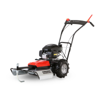
2.3.2 Description of machine and its components
The F-550 brush cutter frame (on
Pic. 3
) is made of a welded steel frame 11 from formed sheet metal, which all essential machine
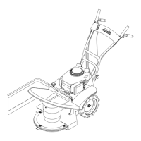
components are attached to. The handlebars are mounted to the frame with screw connections 3 and their height may be adjusted into
six positions. All control elements ( 1 , 2 and 4 ) for safe control of the machine are ergonomically distributed along the handlebars.
The handle 12 is used to firmly grasp and direct the machine during operation. A wheel drive clutch lever 2 is located on the left
side of the handlebars, which controls the motion of the machine forward. On the right side is a tool drive clutch lever 1 equipped with
a safety lock to prevent accidental operation 16 , which turns the work tool (blade) drive on or off. If the operator releases the
handles in an emergency, both of the control levers return to the default position and the engine is disengaged from transmitting force. The
blade drive is equipped with an automatic braking device, which stops the blade
60
in the event of an emergency. Motor speed is controlled
by the throttle lever 4 . Motion is secured by wheels 15 with arrows pattern, which are driven by a worm-gear unit. It provides smooth
shifting of force to the wheel via a belt-driven clutch
(the machine moves forward without jerking)
. The wheel and blade drive transmission
part are covered by plastic housing 9 and 10 . The brake, blade drive clutch, and belt gears in front are also covered from above by a
plastic cover 9 connected by screws to the frame. Pressed on the shaft at the front of the frame is a blade holder with blade 7 . The
blade is fixed and sharp at the ends. The main deck comprises a cover 8 made from hot-dip galvanized
(HDG)
sheet metal, which except
for the front, spans further than the blade to prevent injury to the operator from flying parts of the mowed area. The deck is riveted from
several parts and screwed to the frame. A plastic shroud is fastened between the wheels. During operation, the machine is guided by a
swivel, height-adjustable spur 5 , which is attached to the front of the machine frame.
2.4 User manual
2.4.1 Assembling the machine
Assembly and operating instructions are available from your retailer as a component of pre-sales service!
Handling points when removing the machine from the box (see
Pic. 1
): ahead of the engine behind the square tube 5 on the engine
plate, at the back of the machine frame tube 4 .
2.4.1.1 Machine assembly procedure
Use the following procedure when assembling: (
We recommend that another person be present to assist you during assembly
)
1) According to
Pic. 1
- remove the bag with manuals 2 , spur arm 3 and unfold the paper insert 7 underneath the
handlebars. Hold the machine at the front 5 and back 4 handling points, and remove it from the box.
2) According to
Pic. 3
- remove the screw connections 3 from both sides of the frame tube, remove the handlebars, turn them
around and place them on the tube at the rear frame (select one of the three holes in the handlebars to set their height and one
of the two holes in the frame tube). Tighten the screw joints securely by hand. Control lever cables must not be crossed – this
reduces their life!
3) Remove the tie straps from the bag with manuals and attach the control lever cables at the top of the handlebar tube bend.
Only 2 tie straps are required for fastening.
4) According to
Pic. 2
- remove the paper insert ( 6 in
Pic. 1
) from the front of the main deck cover, tilt the machine backwards
onto the handlebars so the rear frame rests on a mat, and secure the machine from tilting back forward. Remove 2 M8 screw
connections ( 1 and 3 ) holding the cover. Hook the tab 2 on the spur arm 5 into the machine frame groove 4 . Lower
the spur arm so that the holes in the spur arm are concentric with the holes in the machine frame. You will feel light cushioning.
Insert the screws 3 through the holes and attach the nuts 1 . Tighten the screw connection.
2.4.2 Commissioning
The machine may be supplied without engine fluids (depending on various national regulations)!
First, carefully read the engine operating manual
61
! This will help prevent any engine damage.
53
More information about the engine including replacement part numbers can be found at www.honda-engines-eu.com
54
More information about the engine including replacement part numbers can be found at www.briggsandstratton.com
55
More information about the engine including replacement part numbers can be found at www.honda-engines-eu.com
56
Short-term = within one minute
57
Measured according to the Society of Automotive Engineer (SAE) standard J1349
58
Measured according to the Society of Automotive Engineer (SAE) standard J1349
59
Vzhledem ke stále se zvyšujícímu podíliu BIOsložkek v palivu používejte stabilizátor paliva.
60
Automatic brake is an active protective element that increases the safety of the machine.
61
Original engine manual and Czech translation is included in the machine packaging.
22
02/2013
 Loading...