A
bowl, then raise the bowl arms up to normal working position.
With your hand turn the beater, and then measure the distance
between beater and bowl edge. By removing the rear covering,
the bowl arm guide plate is now accessible . Loosen the
screws and move the bowl arm guide plate in the required
direction. Again turn the beater and measure the distance
between beater and bowl. When the bowl has been centred,
fasten the bowl arm guide plate in the new position and screw
on the rear covering.
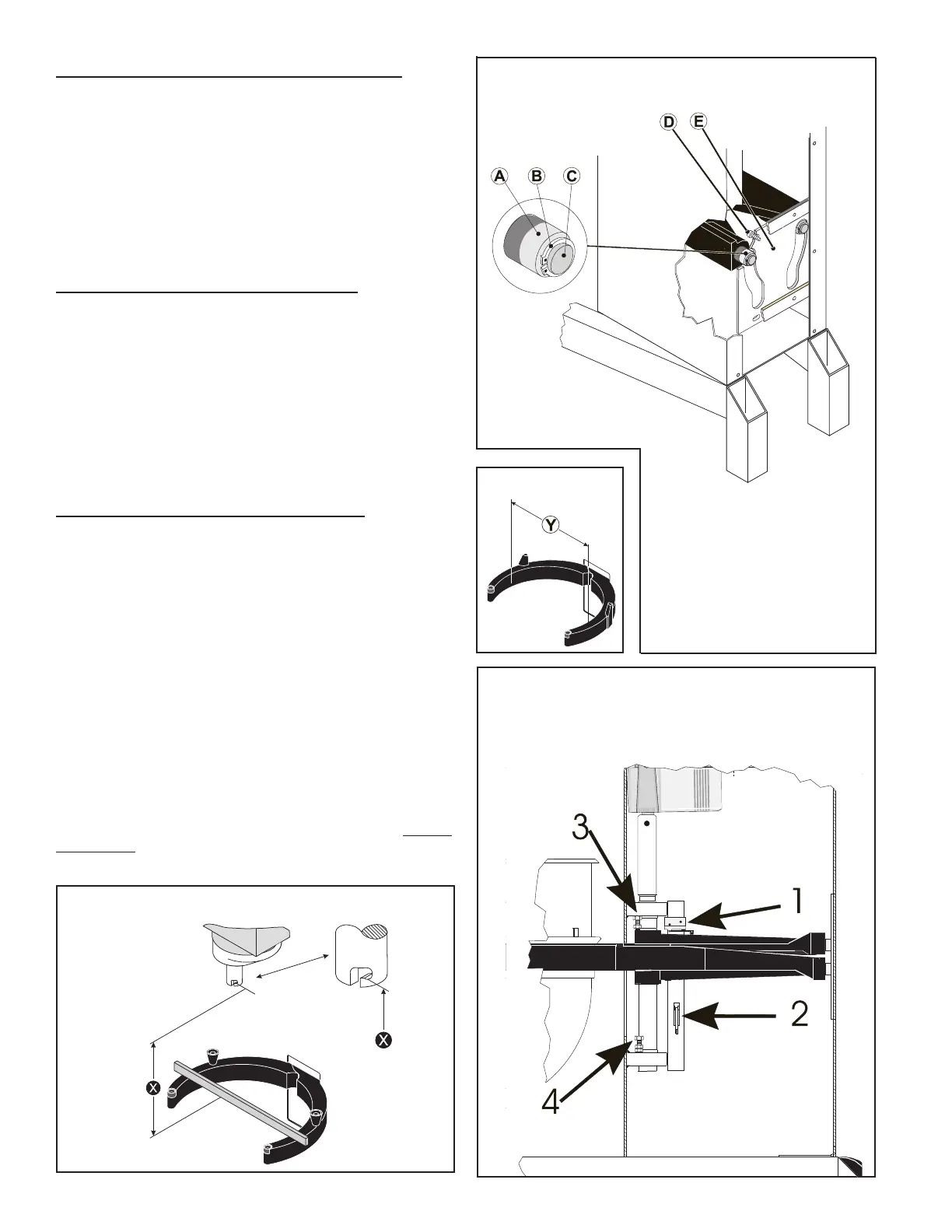
The bowl arms must be raised to normal working position. The
adjusting diameter shall be measured inside between the
bowl arms :
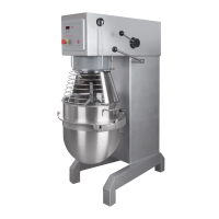
In case the bowl fastening is too loose, remove the lock ring
and draw the bearing from the shaft . The bearing
should be turned 180
and be mounted on the shaft again.
It might be necessary to turn both bearings. At last check the
bowl centering and if necessary, adjust.
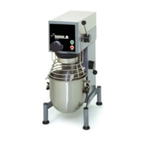
The distance is measured from the bottom side of the
bayonet hole to the surface on the bowl arms on which the bowl
rests The bowl arms must be lifted to normal working
position.
"
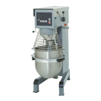
The upper and lower position of the bowl is determined by micro
switch and , . The two mechanical stops consist-
ing of the bolts and are adjusted so that they will be hit
approx. 0.04" after the micro switch, in case the micro switch
should fail.
The lower position is adjusted first; by sliding the en-
tire bracket assembly up or down on the slots on the
bracket (2). The upper position of the bowl arms is ad-
justed by adjusting the up position micro switch mount-
ing bracket (2) up or down; it is of utmost importance
that the stop screw (3) is re-adjusted afterwards.