VC72XX_HW.pdf – Hardware Documentation VC72XX Smart Cameras
1996-2016 Vision Components GmbH Ettlingen, Germany
Note:
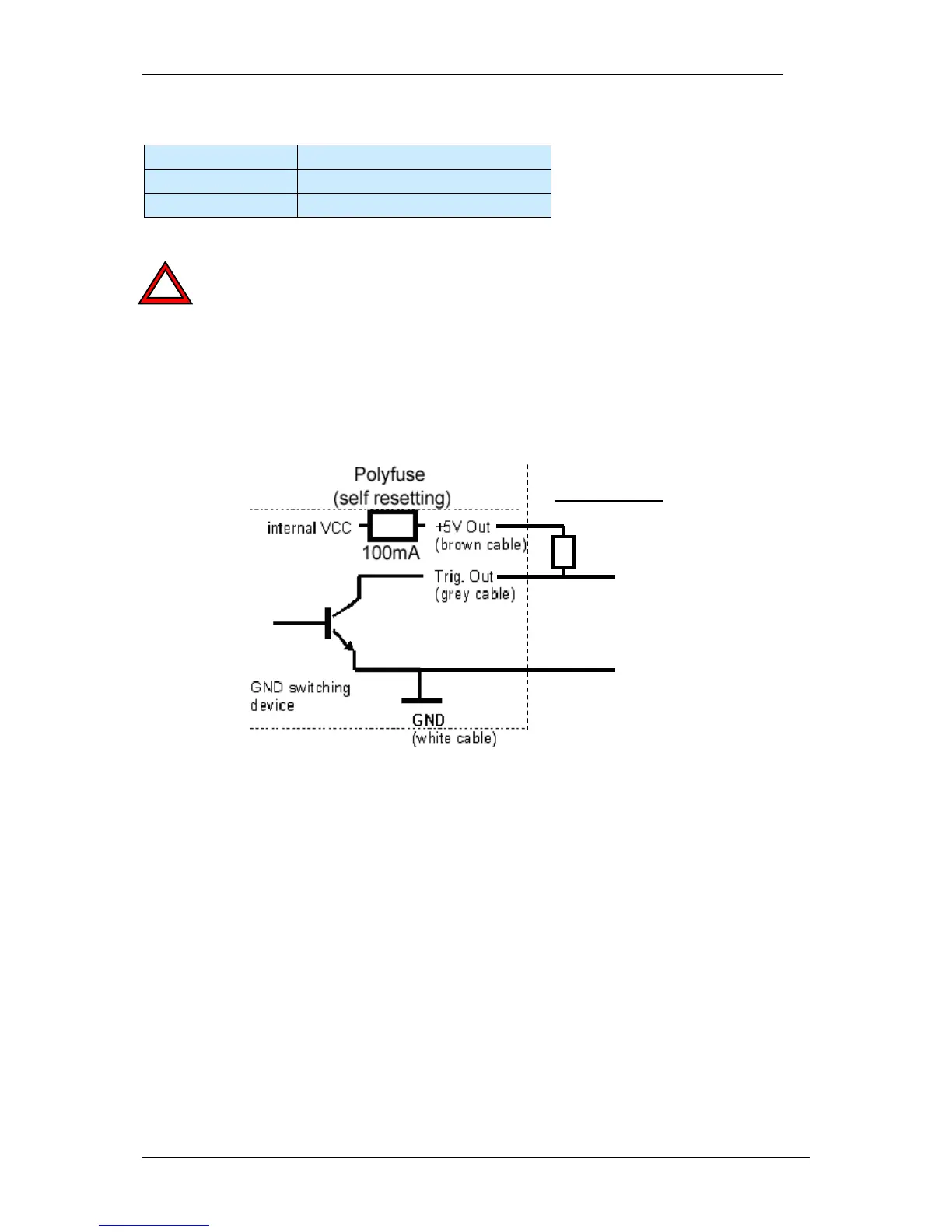
An external pull up resistor is required (for instance 1 kΩ) between Trig Out and +5V (+3.3V*)
out in order to pull the floating trigger output back to high.
The 100 Ω Resistor protecting the TTL trigger output Pin 5 from the VC20XX has been
replaced with a self resetting poly fuse (see the following drawing). The trigger output is
switching to ground (active low). The behavior of the output signal however can be
programmed high or low during exposure (see the “Programming Tutorial” or the “Trigin.c”
demo program).
R pull-up
Trig-Out
GND
External Circuit