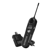
Automotive Short And Open Finder
14
•
Careful attention should be paid to the beeping and ashing speed of the V210 receiver
unit indicators, as these provide the necessa feedback to evaluate the proximity of the
probe sensor to the wire being traced.
•
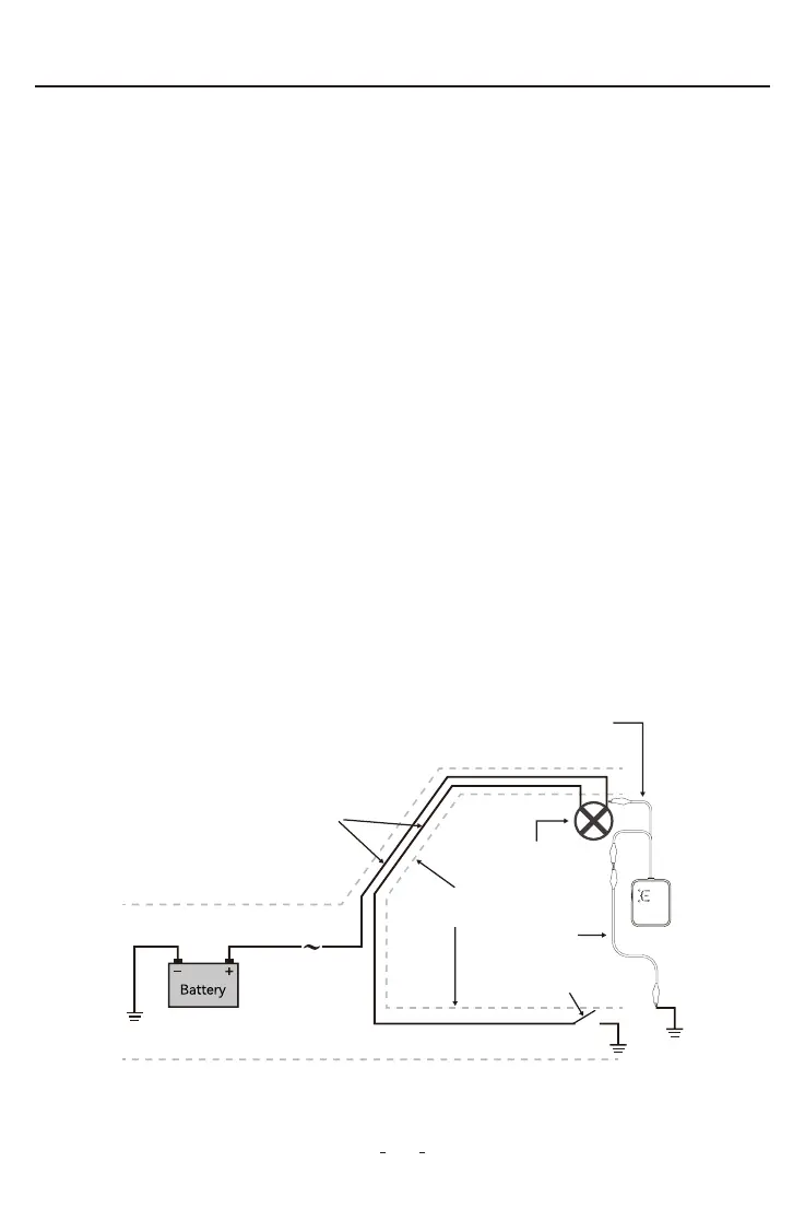
For the cases in which it is suspected the layout of the wires is the cause of a ve
dicult to pick up or weak signal, a dramatic increase of the range can be accomplished
by “spreading” the circuit.
•
The spreading the circuit is achieved by connecting a jumper wire between the live wire
(preferably at a termination point in the circuit such as a light bulb socket, switch, etc.),
and a ground point somewhere else in the vehicle ( see Fig.11 )
When tracing or identifying wires connected to a lightly loaded circuit (low currents),
pickup range is reduced signicantly. A possible solution is, after connecting the V210
transmitter in series with the circuit to trace, is to replace the load (light bulb, module, etc.)
with a direct connection to ground. This allows the V210 transmitter to inject a more
poweul signal which is easier to detect.
This last method should be used only as “last resource” and with the V210 receiver set to a
lower sensitivity, as it could make the pinpointing of the precise location more dicult due
to the much increased range.
2.15 To increase the pickup range when tracing wires
Light
Jumper
Wire
Door switch
Wires shielded
by door frame
Fuse
Box
Positive (Live) and ground
wires running parallel
to each other
Connection of the V210
transmitter at the load using
a jumper wire to ground
Figure 11