Automotive Short And Open Finder
15
•
Always verify that the V210 transmitter is connected in series with the circuit being
tested and that its red indicator light is on, as this conrms a proper connection and will
limit the amount of current owing in the circuit.
•
These stray currents present in the non-shoed branches of the circuit, and depending
on the circuit conguration and physical layout of the wires, could be picked up by the
V210 receiver, making the tracing procedures confusing, and even misleading.
•
The simplest and most eective way to deal with these cases, is to disconnect or remove
all the loads from the circuit being traced (i.e. removing light bulbs in example shown in
( Fig. 12 ).
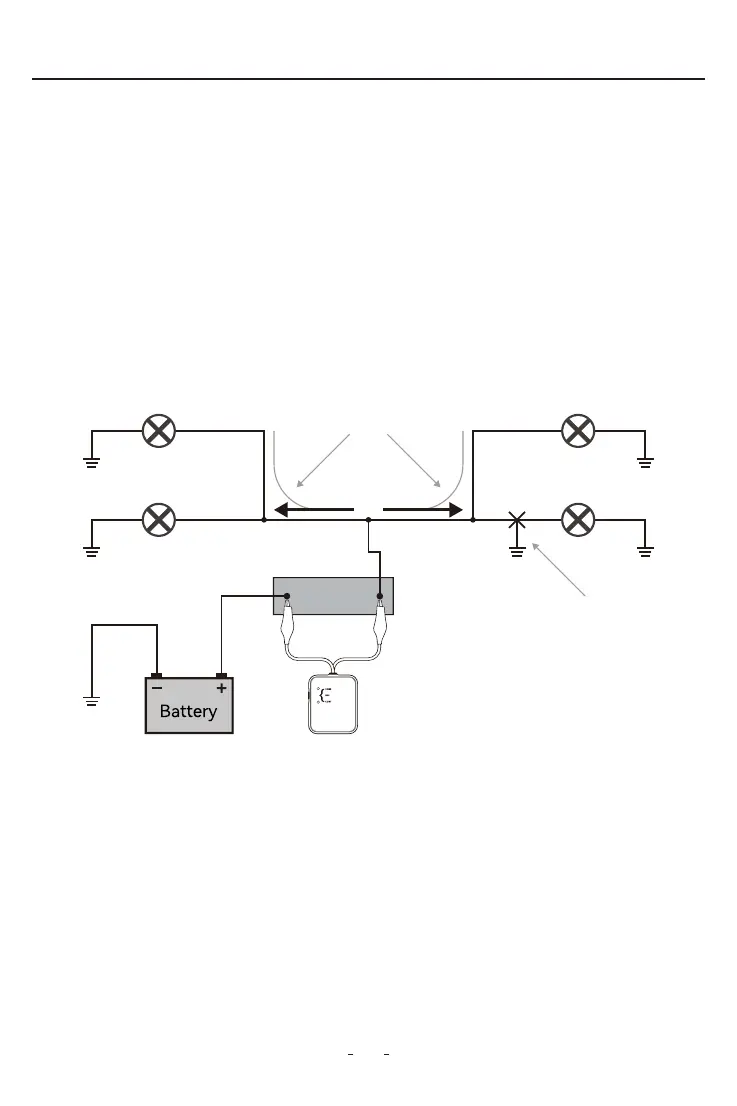
When tracing circuits connected to, or which are powering multiple loads and/or branches
(See Fig. 12), and when these circuits are active or live, the bulk of the current injected
into the circuit by the V210 transmitter will be directed to the shoed branch of the circuit.
However smaller amounts of current (or stray currents) will ow to the other branches as
long these provide a path to ground (i.e. close the circuit).
2.16 Circuits with multiple loads and branches
Figure 12
Light Bulb
Light Bulb
Light Bulb
Current Flow
Sho Circult
Fuse Socket
Light Bulb