Automotive Short And Open Finder
10
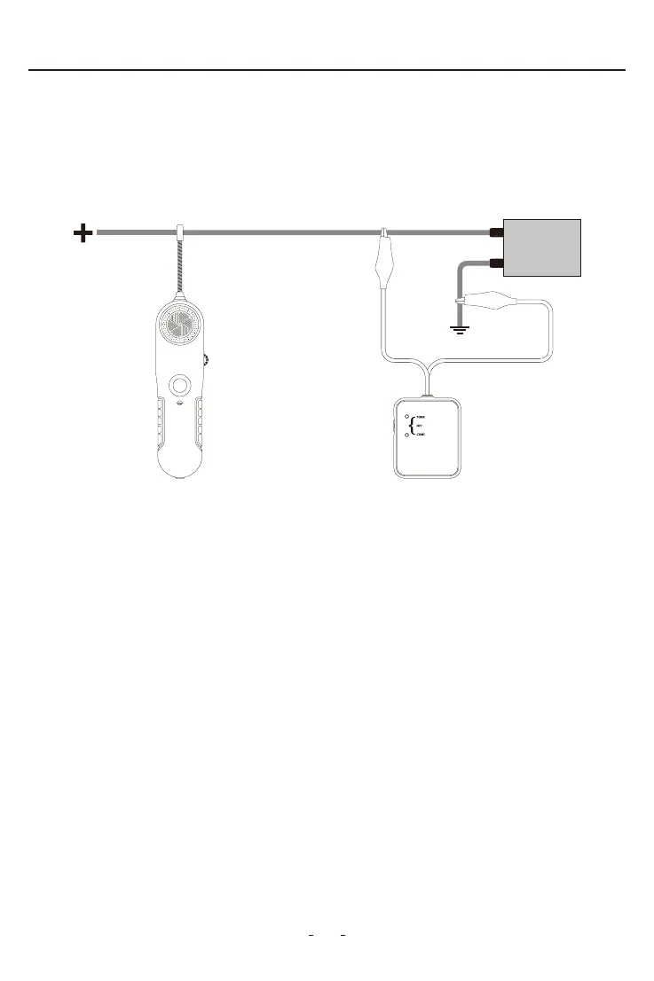
• Tracing wires upstream (from load to supply): If more convenient, wires can also be
traced the other way around, by replacing the load with the V210 transmitter ( Fig. 7 ).
To do this, rst remove power from the circuit, disconnect the load and connect the V210
transmitter in its place. Apply power to the circuit and follow instructions in section 2.8–
Locating Sho Circuits.
• For identifying wires with load connected: Connect the V210 transmitter as described
in section ‘2.8- Locating Sho Circuits’ to the circuit to be identied, then proceed to
scan all suspected wiring with the V210 receiver probe sensor until the tone is at its
maximum. In the case of tightly packed wires (bundles, conduits, etc.), it may be
necessa to spread these apa to facilitate the identication process of a paicular
wire.
Note: Obsee the limits and safety precautions at all times.
2.11 Wire Identication
1. Set the switch of the V210 transmitter to “TONE”, the red LED indicator will light up. If the
red LED does not light up, please check the batte.
2. Switch on the V210 receiver, set the rota switch in middle position. Press and hold
“TEST” button, meanwhile move the probe sensor close to the test lead of the
transmitter.
Figure 7
V210 Receiver V210 Transmitter