12
13
Operation
Operation
Minimum
Current
Press & hold
Trigger
Release
Trigger
Note: that when operating in GTAW (HF and LIFT TIG modes), the power source will
remain activated until the selected down slope time has elapsed
4T Latch mode this mode of welding is mainly used for long welding runs to reduce
operator fatigue. In this mode the operator can press and release the torch trigger and
the output will remain active. To deactivate the power source, the trigger switch must
again be pressed and released, thus eliminating the need for the operator to hold the
torch trigger.
12. Trigger Mode Control Button (HF TIG and LIFT TIG Mode only)
The trigger mode control is used to switch the functionality of the torch trigger between
2T and 4T.
output to be active.
Press and hold the torch trigger to activate the power source (weld). Release the torch
trigger switch to cease welding.
2T Normal Mode In this mode, the torch trigger must remain pressed for thewelding
9. Frequency Indicator (Hz)
Frequency indicator, when the setting programm in pulse frequency ,this indicator will
be on.
11. Thermal Overload Indicator Light
This welding power source is protected by a self resetting thermostat. The indicator will
illuminate if the duty cycle of the power source has been exceeded. Should the thermal
overload indicator illuminate the output of the power source will be disabled. Once the
power source cools down this light will go OFF and the over temperature condition will
automatically reset. Note that the mains power switch should remain in the on position
such that the fan continues to operate thus allowing the unit to cool sufficiently. Do not
switch the unit off should a thermal overload condition be present.
10. Power ON Indicator
The POWER ON indicator illuminates when the ON/OFF switch is in the ON position and
the correct mains voltage is present.
13. Process Selection Button
The process selection control is used to select the desired welding mode. Three
modes are available, MMA (Stick),GTAW (TIG) and CUT modes.
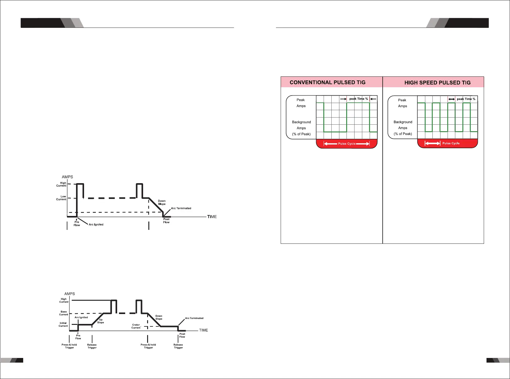
14. Pulse Button
Press the PULSE button to toggle Pulse On and OFF.
Typically from 1 to 10 PPS. Provides a heating
and cooling effect on the weld puddle and can
reduce distortion by lowering the average
amperage. This heating and cooling effect also
produces a distinct ripple pattern in the weld
bead. The relationship between pulse frequency
and travel speed determines the distance
between the ripples. Slow pulsing can also be
coordinated with filler metal addition and
increase overall control of the weld puddle
In excess of 40 PPS, Pulsed TIG becomes more
audible than visible-causing increased puddle
agitation for a better as-welded microstructure.
Pulsing the weld current at high speeds-between
a high Peak and a low Background amperage-
can also constrict and focus the arc.This results
in maximum arc stability, increased penetration
and increased travel speeds(Common Range:
100-500 PPS).
The Arc-Sharpening effects of high speed
pulsing are expanded to new dimensions. The
ability to pulse at 5,000PPS further enhances
arc stability and concentration potential-which
is extre mely beneficial to automation where
maximum travel tspeeds are required.
15. Programming Parameter Indicators
These indicator lights will illuminate when programming.
16. Positive Welding Terminal
Positive Welding Terminal. Welding current flows from the Power Source via heavy
duty bayonet type terminals. It is essential, however, that the male plug is inserted
and turned securely to achieve a sound electrical connection.
and turned securely to achieve a sound electrical connection.
17. Negative Welding Terminal
Negative Welding Terminal. Welding current flows from the Power Source via heavy
duty bayonet type terminals. It is essential, however, that the male plug is inserted
18. Shielding Gas Outlet
The Shielding Gas Outlet located on the front panel is a fast connection of a suitable
TIG Torch.
AC/DC PLASMA SERIES EQUIPMENTAC/DC PLASMA SERIES EQUIPMENT