14
15
Operation
Operation
CAUTION
Loose welding terminal connections can cause overheating and result in the male plug
being fused in the terminal.
22. Power switch
before using the machine. Pull the switch to the closure state of “AN” to operate the
machine, and pull the switch to “AUS” after use. Turn off the power input, and the machine
will stop operating.
21. Gas input port
The gas port is connected with the gas valve output port. After connection, check whether
there is gas leakage.
20. Program downloading port
Change the program downloading connection port, and use the plastic cover to prevent
the dust from polluting and oxidizing the port after use.
19. 5 Pin Control Socket
The 5 pin receptacle is used to connect a trigger switch or remote control to the welding
Power Source circuitry:
To make connections, align keyway, insert plug, and rotate threaded collar fully clockwise.
1
2
3
4
5
9
11
6
7
8
13
12
10
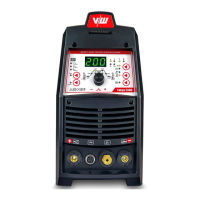
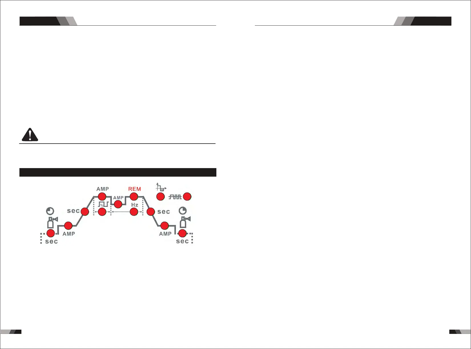
3.2 Control Panel
.Gas Pre-Flow 1
Absolute setting range 0.1s to 5s (0.1S increments)
This parameter operates in TIG modes only and is used to provide gas to the weld zone
prior to striking the arc, once the torch trigger switch has been pressed. This control is
used to dramatically reduce weld porosity at the start of a weld.
2.Initial Current
The main current Setting range 10AMP to 200AMP
This parameter operates in (4T) TIG modes only and is used to set the start current for TIG.
The Start Current remains on until the torch trigger switch is released after it has been
depressed.
Note: The maximum initial current available will be limited to the set value of the base
3.Up Slope
Setting ranges :0.1S-10S (0.1S increments)
This parameter operates in (2T and 4T) TIG modes only and is used to set the time for the
weld current to ramp up, after the torch trigger switch has been pressed then released,
from Initial Current to High or base current.
4.Peak Current
Setting ranges
10AMP to 200AMP (DC TIG mode), 10 to 200A (AC HF TIG mode)
This parameter sets the TIG WELD current. This parameter also sets the STICK weld
current.
5.Base Current
Setting ranges
10AMP to 200AMP (DC TIG mode), 10AMP to 200AMP (AC HF TIG mode)
Secondary current (TIG)/pulse pause current.
6.Down Slope
Setting ranges 0.1-10s
This parameter operates in TIG modes only and is used to set the time for the weld current
to ramp down, after the torch trigger switch has been pressed to end current. This control
is used to eliminate the crater that can form at the completion of a weld.
7.End current
Setting ranges 10A-200A
This parameter operates in (4T) TIG modes only and is used to set the finish current for TIG.
The end Current remains ON until the torch trigger switch is released after it has been
depressed.
Note: The maximum crater current available will be limited to the set value of the base
current.
8.Post Flow
9. Remote Control
Setting ranges 1-10S
The system independently identifies the remote control, and when the indicator light is
on, the welding current can be adjusted by remote (foot or welding gun).
This parameter operates in TIG modes only and is used to adjust the post gas flow
time once the arc has extinguished. This control is used to dramatically reduce
oxidation of the tungsten electrode.
10.Pulse Width
Setting ranges 10%-90%
Thi s p ara mete r s ets t he perc entage on tim e o f t he PUL SE FREQ UENC Y for Hig h
weld current when the PULSE is ON.
11.Pulse Frequency
Setting ranges 1HZ -200HZ
This parameter sets the PULSE FREQUENCY when the PULSE is ON.
AC/DC PLASMA SERIES EQUIPMENTAC/DC PLASMA SERIES EQUIPMENT