TCI-C-Universal Controller
Doc: 70-00-0123, Date: 20091020 © Vector Controls GmbH Page 17
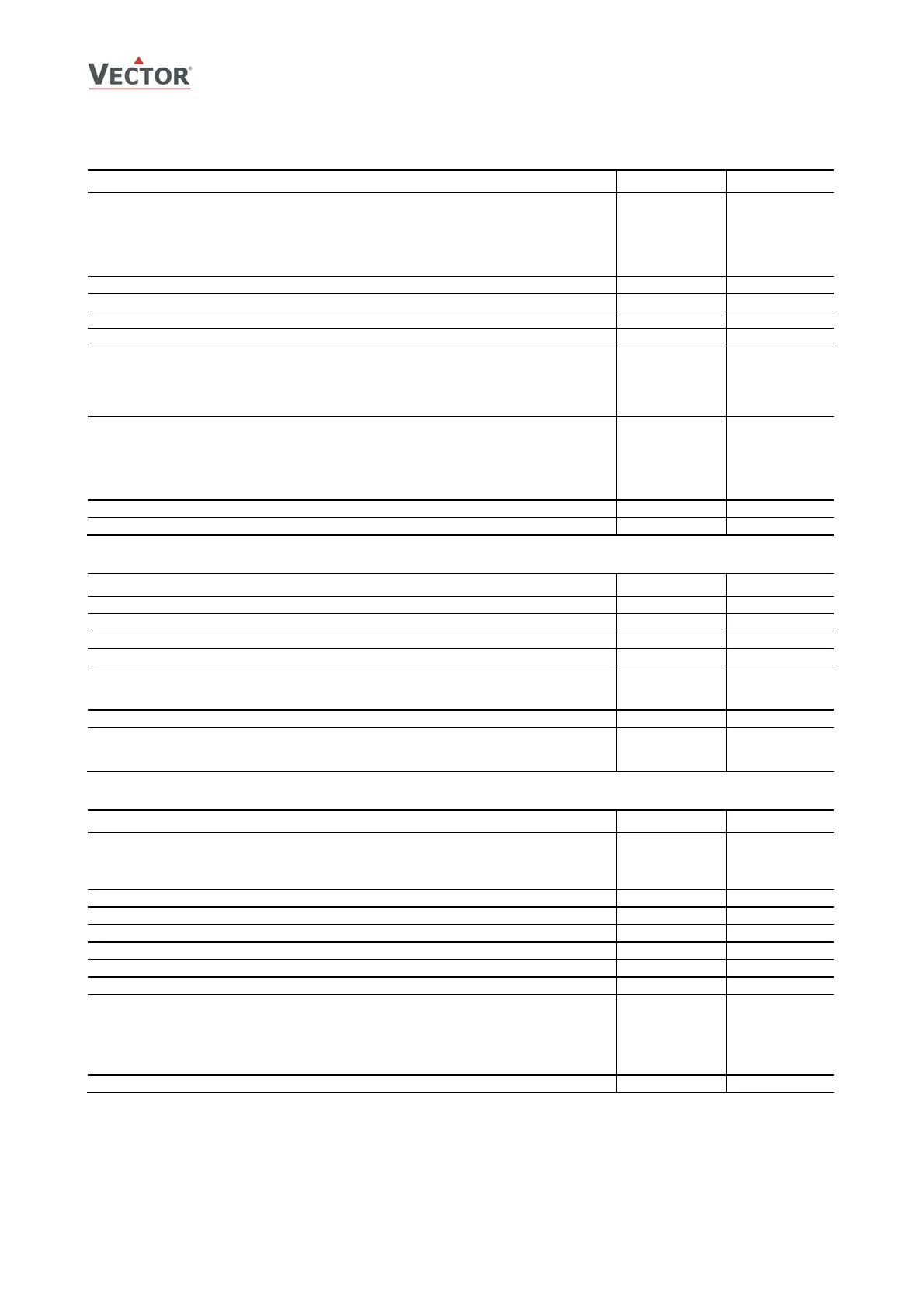
LP: Control parameters (1L to 2L)
Parameter
Description
Range Default
1L 00 Select controls input:
0 = Control loop disabled
1 = Universal input 1
2 = Universal input 2
3 = Universal input 3
4 = Temperature input (PT1000)
0…4 1
1L 01 Minimum set point limit for heating
Acc input
10°C (50°F)
1L 02 Maximum set point limit for heating
Acc input
28°C (82°F)
1L 03 Minimum set point limit for cooling
Acc input
18°C (64°F)
1L 04 Maximum set point limit for cooling
Acc input
34°C (92°F)
1L 05 Enable setpoint compensation with auxiliary function
0 = setpoint compensation is disabled
1 = Winter Compensation only
2 = Summer compensation only
3 = Winter and summer compensation
0…3 0
1L 06 Select setpoint input:
0 = Normal setpoint of control loop
1 = Combined setpoint with other control loop
2 = cascade with reverse sequence of primary loop only
3 = cascade with direct sequence of primary loop only
4 = cascade with both reverse and direct of sequence of prim. loop
0…4 0
1L 07 Standby set point shift Acc input 5.0°C (10°F)
1L 08 Dead zone between heating & cooling set point X
DZ
Acc input
1.0° (2°F)
PID Control Sequence
Parameter Description Range Default
1L 09 Offset for heating PID sequence Acc input 0
1L 10 Offset for cooling PID sequence Acc input 0
1L 11 P – band heating X
PH
Acc input 2.0°C (4.0°F)
1L 12 P – band cooling X
PC
Acc input 2.0° (4.0°F)
1L 13 K
IH
, Integral gain heating, in 0.1 steps, 0 disables ID part
low value = slow reaction
high value = fast reaction
0…25.5 0.0
1L 14 K
IC
, Integral gain cooling, in 0.1 steps, 0 disables I part 0…25.5 0.0
1L 15 T
I
, measuring interval integral
low value = fast reaction
high value = slow reaction
0…255 1 sec
Digital Control Sequence
Parameter Description Range Default
1L 16 Action of stages
0 = Cumulative: 1. Q
H1
, 2. Q
H1
+Q
H2
1 = Single: 1. Q
H1
, 2. Q
H2
2 = Digital: 1. Q
H1
, 2. Q
H2
, 3. Q
H1
+ Q
H2
0…2 0
1L 17 Offset for reverse (heating) binary sequences Acc input 0.0° (0.0°F)
1L 18 Offset for direct (cooling) binary sequences Acc input 0.0° (0.0°F)
1L 19 Switching span heating Acc input 1.0° (2.0°F)
1L 20 Switching span cooling Acc input 1.0° (2.0°F)
1L 21 Switching hysteresis X
H
Acc input 0.5° (1.0°F)
1L 22 Switching delay min running and min stopping time for binary sequences 0…255s 10s
1L 23
Reverse / direct sequence follows heat –
cool state of controlle
OFF = control sequences activate based on demand and do not follow
heat – cool state of controller
ON = control sequence follow heat cool state. Reverse sequence will
only be active in heating mode, direct sequences in cooling mode
of controller.
ON, OFF OFF
1L 24
Delay for heat –
cool changeover in case above parameter is OFF
0…255 min 5 min