TCI-C-Universal Controller
Doc: 70-00-0123, Date: 20091020 © Vector Controls GmbH Page 9
Control Functions
Depending on product version 1 or 2 independent control loops are available. Each control loop may utilize 6 binary and 2
PID control sequences. Control loop and sequences are activated when defining output parameters.
Manipulation of the set point
Standby set point shift X
SBY
: This function shifts the set point while the operation mode is standby. The heating set
point W
H
is reduced and the cooling set point W
C
increased by the value of the standby set point shift X
SBY
.
Dead Zone Span X
DZ
: The dead zone span lies between the heating and the cooling set point.
Minimum and Maximum Set Point Limits: Limits the adjustable range of the loop set point. The limits for heating and
cooling sequence may be chosen individually.
Cascade Control: The output of the primary control loop determines the set point of the secondary control loop. It is
possible to choose only the direct or reverse sequence or both of them. The output of the set point providing control loop
is spanned between the minimum and maximum set point limits. The set point limits for heating and cooling sequence are
defined individually.
Setpoint Compensation: Shift the set point either towards the set point minimum (negative shift) or the set point
maximum (positive shift) depending on an external input signal. This is done to compensate the set point due to a change
in the environment. It is most commonly applied to outside temperature. Summer-Winter compensation is activated
through parameter 1L05 or 2L05.
FU00 selects the compensation input signal, either external temperature or analog input.
The winter compensation is active when the outside temperature drops below the upper limit of winter compensation
FU03. Depending on parameter FU01, the setpoint is now shifted towards the heating setpoint minimum or maximum.
The maximal compensation is reached when the temperature reaches the lower limit FU02. The actual set point will in
this case be equal to the minimum heating set point limit for a negative shift or the maximum set point limit for a positive
shift.
The summer compensation is active when the outside temperature exceeds the lower limit for summer compensation
FU05. Depending on parameter FU04, the setpoint is now shifted towards the cooling setpoint minimum or maximum. It
reaches its maximum when the temperature equals the upper limit FU06.
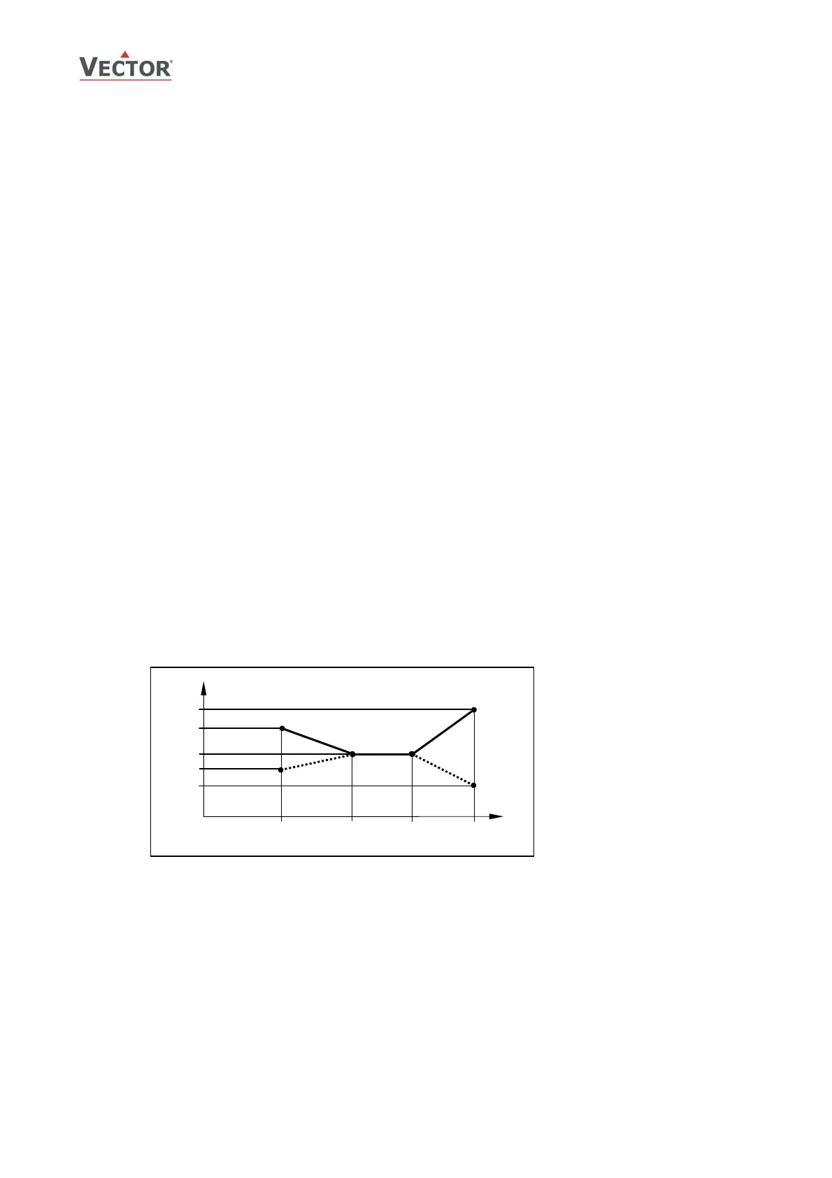
Example: Summer – Winter compensation active in loop 1. 1L05 = 3
Winter Compensation
Summer Compensation
1L02
[°C, F]
U [V, mA]
FU02
FU01 = ON
FU03
1L01
FU01 = OFF
Setpoint
FU04 = ON
1L04
FU05
FU06
W
1L03
Fu04 = OFF