Doc: 70-00-0792B V1.3, 20220830 © Vector Controls GmbH, Switzerland Page 14-34
Subject to change without notice www.vectorcontrols.com
5.2 Setting controller parameter with user interface
Entering the password protected parameter menu
1. Press the up ( ) and down ( ) button for at least 3 seconds.
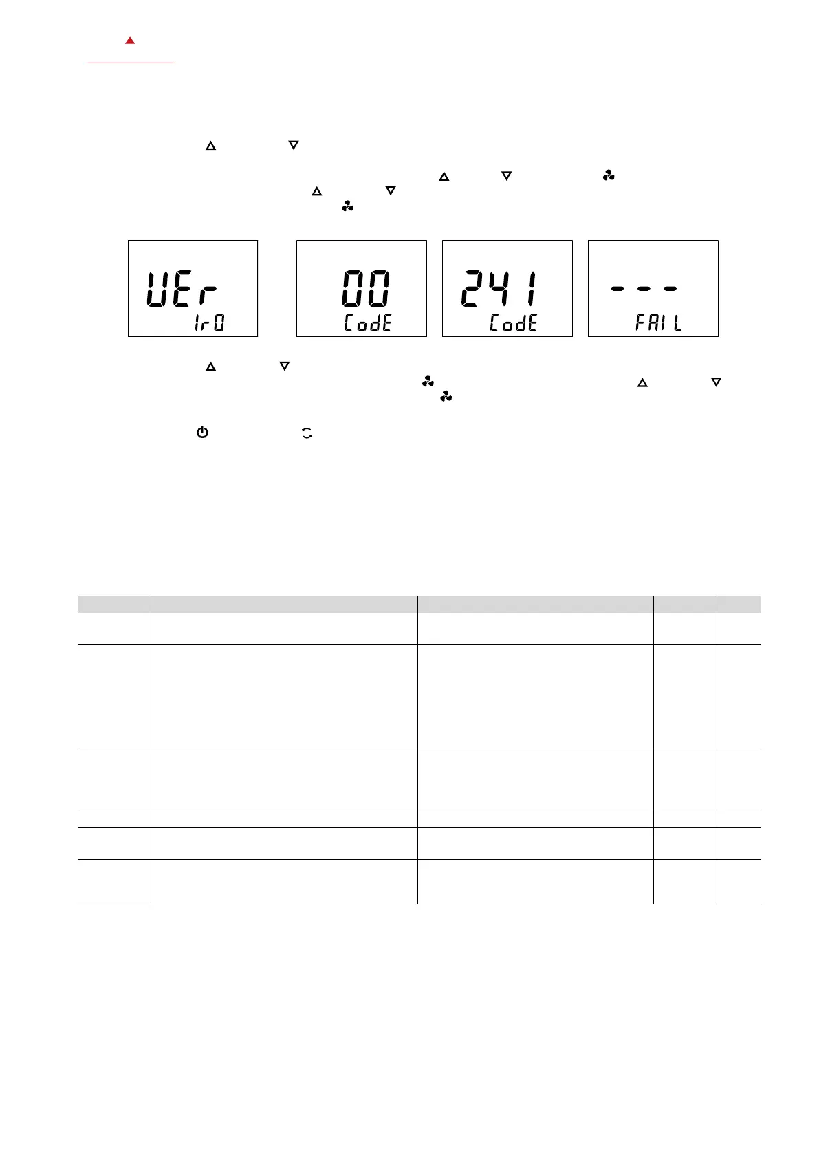
2. The software version is displayed.
3. To continue to the password menu, press ether the up ( ), down ( ) or fan button ( ).
4. Enter the code 241 with the up ( ) or down ( ) button.
5. Confirm the code with the fan button ( ).
Software version (example)
Setting parameters
1. Press the up ( ) or down ( ) button to select the desired parameter.
2. To set the value of parameter, press the fan button ( ) then adjust the value with the up ( ) or down ( )
button and save the setting by pressing the fan button ( ) again.
Exit the parameter menu
Press the Operating ( ) or Controlling ( ) Mode button to leave the parameter menu.
5.3 Modbus settings (TRA-F121-A only)
5.3.1 Parameter P00x overview
Each Modbus slave device needs a unique device address (ID) in the network. It can be set with P001. All other Modbus
network properties can be set with parameter P002, P003 and P006.
With parameter P005 the write access to the parameter via Modbus master is disabled (except P005 can always be
written).
P004 is not used.
Modbus device address (ID)
0 = 2400 BPS
1 = 4800 BPS
2 = 9600 BPS
3 = 19200 BPS
4 = 38400 BPS
5 = 57600 BPS
6 = 115200 BPS
0 = NO Parity, 2 stop bits
1 = EVEN Parity, 1 stop bit
2 = ODD Parity, 1 stop bit
3 = NO Parity, 1 stop bit
Not used (always 1 = RTU)
Allow changing of parameter settings through
communication
0 = Not allowed (except P005)
1 = Allowed
0 = No offset
1 = PLC address style (+1 address
offset)
 Loading...


