2.6 VN5610A
Manual VN5610/VN5610A Version 2.0 28
Note
The VN5610A requires at least 8 V to power up. Afterwards the power supply can
be reduced to 6 V for operation (typ. 12 V DC). The need of an external power sup-
ply depends on the Ethernet configuration (see table).
Ethernet
Configuration
Channel 1
Disabled 100BASE-T1 100BASE-TX 1000BASE-T
Channel 2
Disabled O O O O
100BASE-T1 O O O X
100BASE-TX O O O X
1000BASE-T O X X X
O: bus-powered (also when both CAN channels in use), X: external power supply recommended.
Note: CAN itself requires no external power supply.
> USB
Connect your PC and the VN5610A over USB to install and to use the device with
measurement applications (CANoe, CANalyzer). Use the USB2.0 compliant
cable found in the delivery (USB extension cables may generate faults between
the PC and the device). Connect the device directly to a USB port at your PC or
use a USB hub with its own power supply (self-powered). The device can also be
powered via this connector.
> Host (Ethernet)
Host connector. Reserved for future purposes.
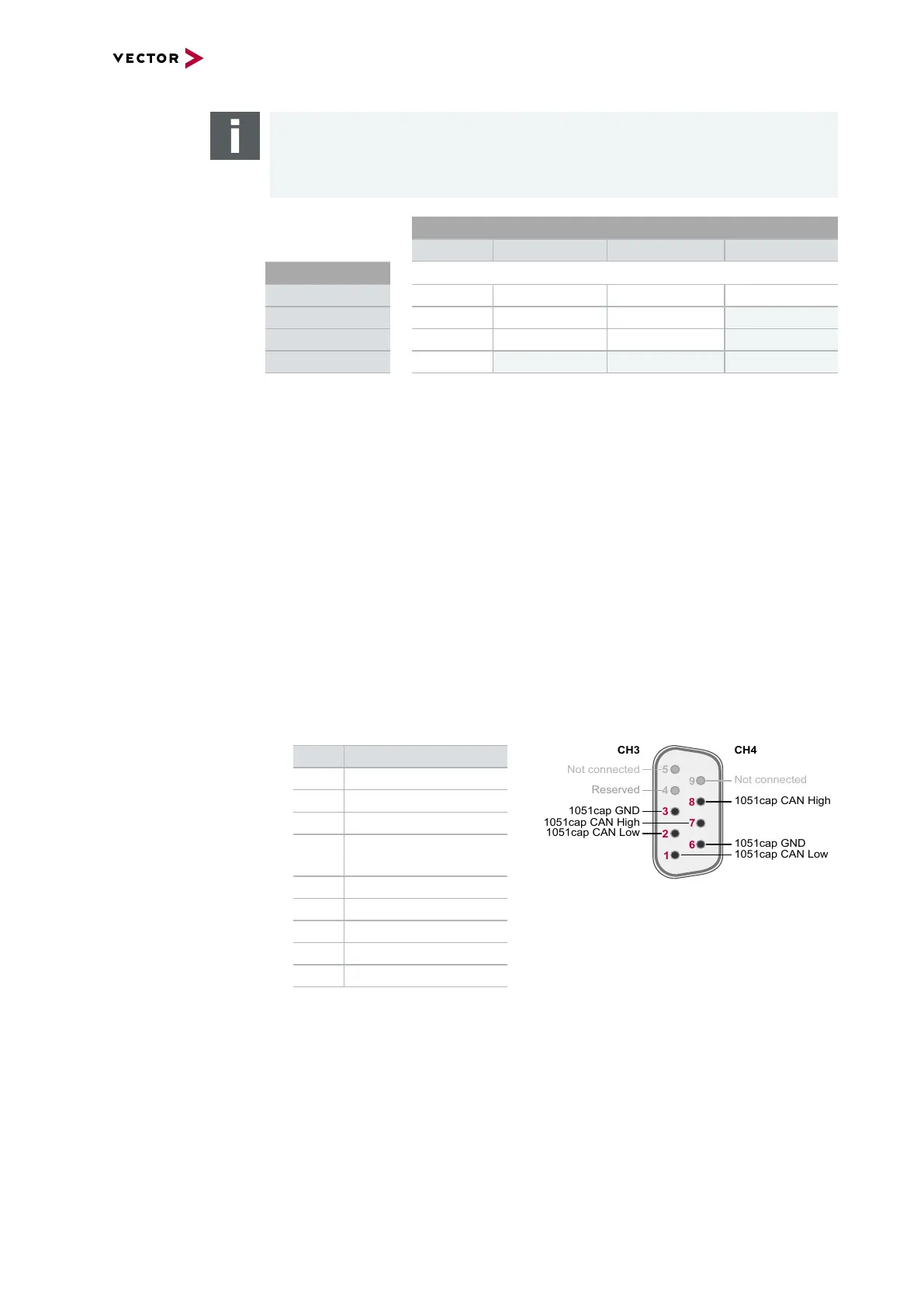
> CAN CH3/4 (D-SUB9)
D-SUB connector with two CAN channels. Use the CANcable 2Y to access both
channels on separate D-SUB9 connectors (see accessories manual, part number
05075).
Pin Assignment
1 CH4 CAN Low
2 CH3 CAN Low
3 CH3 GND
4 Reserved.
Please do not use.
5 Not connected
6 CH4 GND
7 CH3 CAN High
8 CH4 CAN High
9 Not connected