2.5 VN5610
Manual VN5610/VN5610A Version 2.0 21
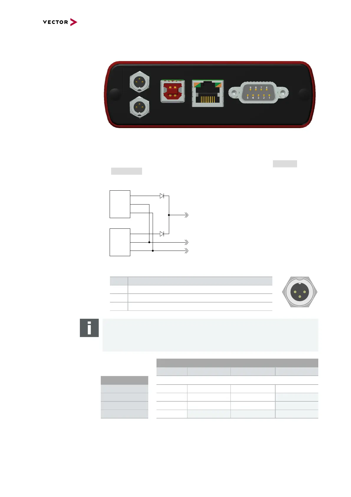
2.5.2 Connectors USB Side
Device connectors
Figure 12: Connectors on the USBside
> 2x Power/Sync (Binder connector)
The VN5610 has two power/sync connectors (Binder type 711) which can be used
for time synchronization of different Vector devices (see section Time Syn-
chronization on page 43) or for power. It does not matter which connector is used
to supply the device.
VCC
1
2
3
Power
1
2
3
Sync
GND
Sync
GND
Power/Sync
Power/Sync
SYNC
GND
Power
Figure 13: Internal wiring of the power/sync connector
Pin Assignment
1 Power supply (6 V … 50 V DC, typ. 12 V)
2 Synchronization line
3 Ground
Note
The VN5610 requires at least 8 V to power up. Afterwards the power supply can be
reduced to 6 V for operation (typ. 12 V DC). The need of an external power supply
depends on the Ethernet configuration (see table).
Ethernet
Configuration
Channel 1
Disabled 100BASE-T1 100BASE-TX 1000BASE-T
Channel 2
Disabled O O O O
100BASE-T1 O O O X
100BASE-TX O O O X
1000BASE-T O X X X
O: bus-powered (also when both CAN channels in use), X: external power supply recommended.
Note: CAN itself requires no external power supply.