3 Vac System Field Wiring - TLS-350/350R Consoles Connecting Pump Control to TLS-350/350R Console
3-2
Console Setup:
• Pump Sense setup - assign each tank to Pump Sense device
• Output Relay setup - select ‘Pump Control Output’
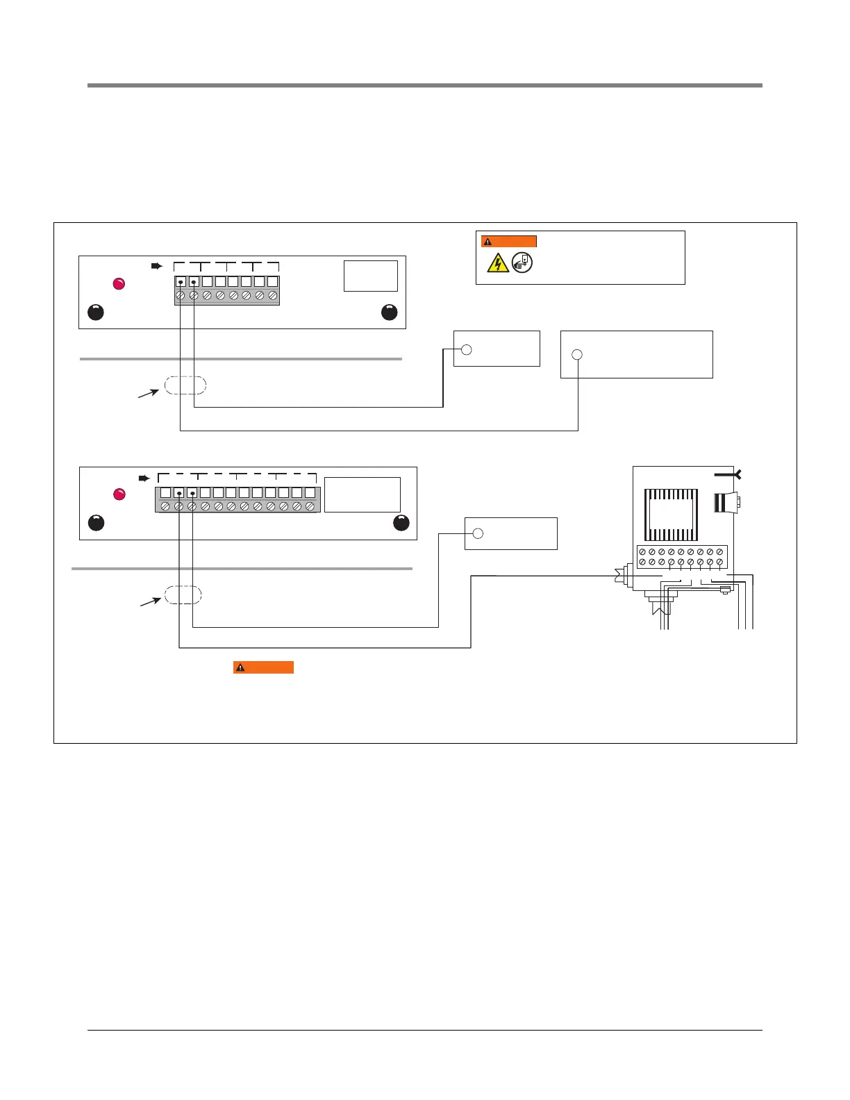
Figure 3-2.- Connecting Pump Sense And 4-Relay Modules - Red Jacket Pumps
Power Panel
Power Panel
AC Neutral
110 Vac
Self-Serve System
or Dispenser switched
hot 120 Vac
Pump Control
RELAY
RELAY RATINGS
Form C Contacts
120 VAC, 2A Max; or
24 VDC, 2A Max.
1 2
4-RELAY OUTPUT MODULE
NC NO C
1
NC NO C
2 3
NC NO C
3
NC NO C
44
Console
Rigid Conduit (enters
Console through a
Power Bay knockout)
INPUT RATING
120 VAC
.15 AMP MAX
PUMP SENSE MODULE
PI PR PI PR PI PR PI PR
PUMP
1 2 3 4
Console
PUMP IN (PI)
PUMP RETURN (PR)
Rigid Conduit (enters
Console through a
Power Bay knockout)
From
Beaker Panel
Pump Power
To
Submersible
Pump
Product
Relay
Red Jacket
Remote Control Box
M2 M1 N L1 L2
S2
In locations using pump controls rated for 240 VAC,
use the appropriate TLS-350 Console Modules and
wiring, rated for 240 Volts.
WARNING
WARNING
OFF
DISCONNECT, LOCK OUT, AND TAG POWER
TO THE STP/SELF SERV SYS./DISPENSER
AT THE POWER PANEL BEFORE CONNECTING
WIRING TO THIS EQUIPMENT.
WARNING
OFF

 Loading...