1-1
1 Introduction
These instructions describe the installation of Veeder-Root Vacuum sensors in a STP containment sump to monitor
the interstitial space of:
• Double-wall product lines
• Double-wall vapor return lines
• Double-wall tank vent lines
• Double-wall tanks*
• Double-wall containment sumps
*Double-walled tanks must provide access for installation of a liquid sensor at the lowest point of the interstice.
Product Marking Information
RELATED DOCUMENTS
Documents Required to Install Equipment
This intrinsically safe apparatus is only for use as part of a Veeder-Root Automatic Tank Gauging System (ATG
Console with probes and sensors). To install intrinsically safe apparatus, use the specific control drawing that
appears on the nameplate of the applicable associated apparatus (ATG Console):
The control drawings contain information related to the correct installation of the overall intrinsically Safe System.
This includes information such as maximum number of apparatus, specific apparatus allowed in the system,
maximum cable lengths, references to codes, proper grounding and so on. Control drawings can be found at
veeder.com.
RELATED MANUALS
TLS-3XX Setup Manual 576013-623
V-R Sensor Operability Testing Guide 577013-814
Vacuum Sensor System Troubleshooting Manual 577013-873
TLS-450PLUS/TLS4 Operator's Manual 577014-110
TLS-450PLUS Consoles Module Replacement 577014-077
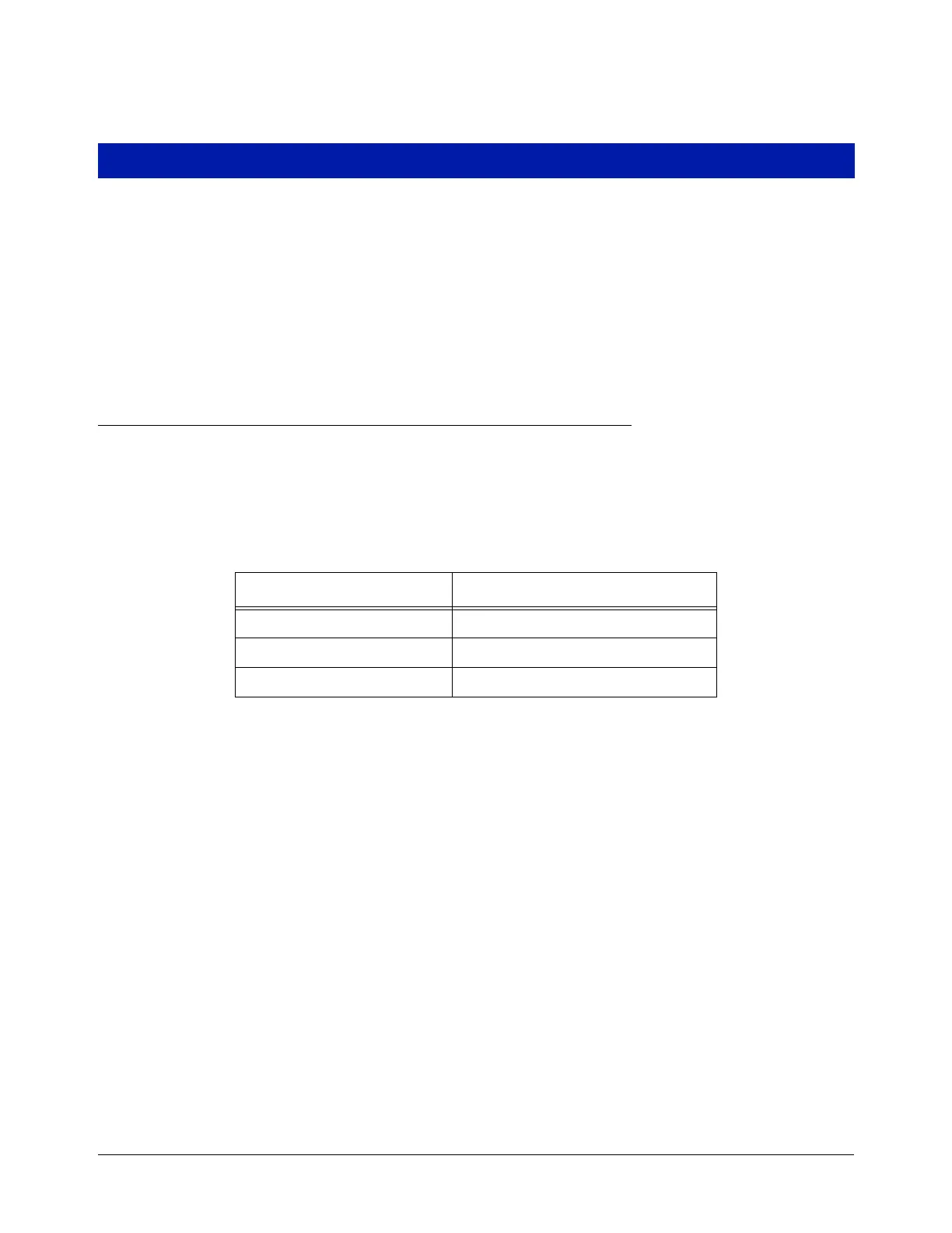
Associated Apparatus UL/cUL Control Drawing Number
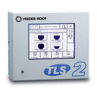
TLS-350, TLS-350R 331940-011
TLS-450/8600 Consoles 331940-008
TLS-XB/8603 331940-019

 Loading...