Home
Veeder-Root
Measuring Instruments
TLS-350R PLUS
Veeder-Root TLS-350R PLUS Installation Guide
4
of 1
of 1 rating
45 pages
Give review
Manual
Specs
To Next Page
To Next Page
To Previous Page
To Previous Page
Loading...
6
Vac System Testing - TLS-450PLUS Console
Vac Sensor Setup
6-4
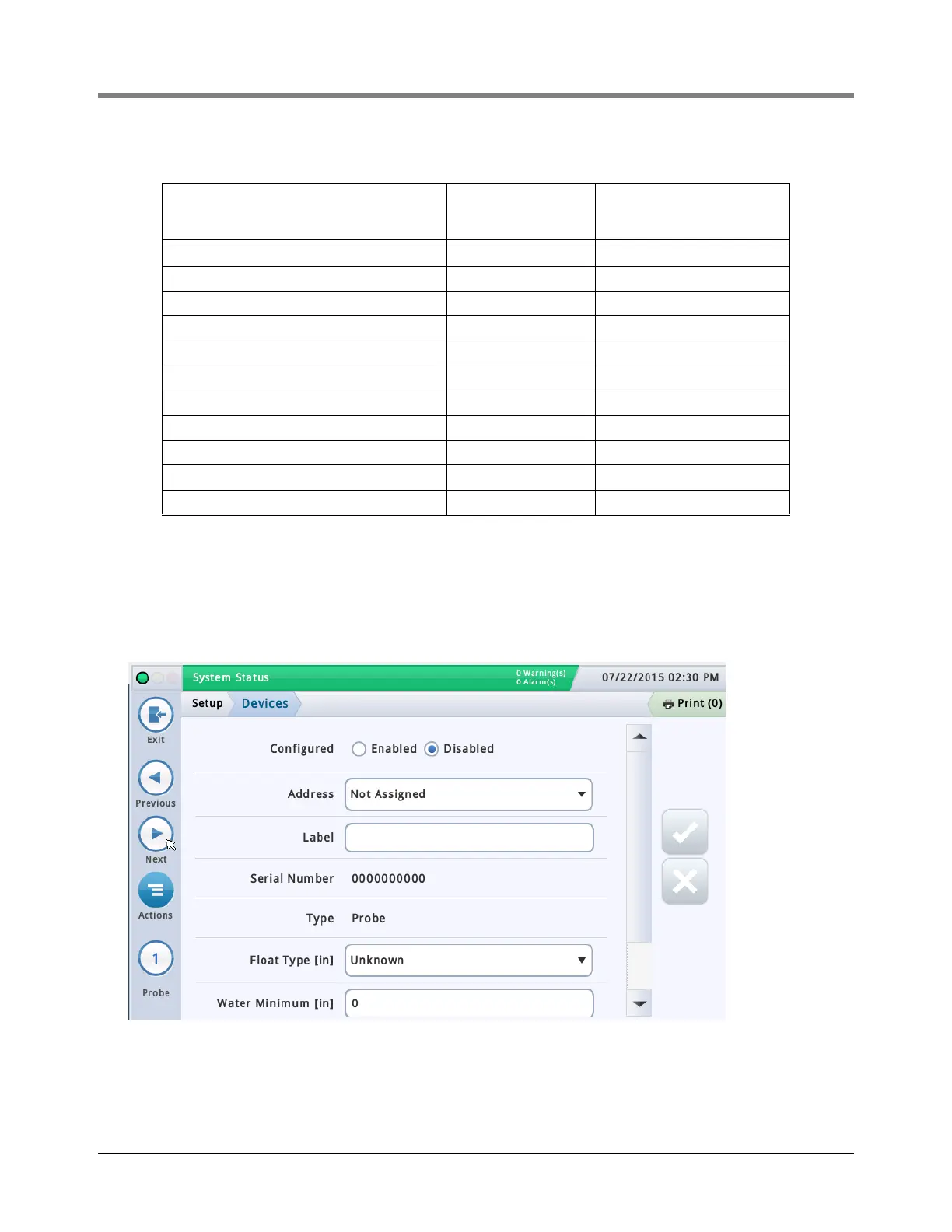
PERFORMING VAC SENSOR SETUP
After filling in the Vac Sensor Zone Worksheet, setup each of th
e Vac Sensors as follows.
1.
Go to
the
Menu>Setup>Devices
screen.
Table 6-2.- Vac Sensor Zo
ne Worksheet
Vac Sensor Monitored Zone Description
Address
(Box.Slot.Channel)
(e
.g
.,
B
1.S1.1)
Calculated Zone
V
olume
(Gallons)
38
40
Table of Contents
Default Chapter
3
Table of Contents
3
1 Introduction
5
Product Marking Information
5
Related Documents
5
Related Manuals
5
Safety Warnings
7
Safety Precautions
7
Before You Begin
8
Hardware Requirements for Vac Sensors - Verifying Installation
9
TLS-350/TLS-350R Consoles
9
TLS-450PLUS Console
9
Stp/Tank
9
Available Vac Sensor Kits
9
How to Use this Manual
10
2 Vac Sensor Installation
11
Overview
11
Figure 2-1.- Installation Example of Four Vac Sensor W/Tank Interstitial Monitoring
11
Field Assembling Vac Sensor/Vac Float Modules
12
Figure 2-2.- Vac Sensor Assembly Dimensions
12
Figure 2-3.- Attaching Four Vac Sensors/Floats to the Housing
13
Figure 2-4.- Vac Sensor/Vac Float Tubing Connections
14
Figure 2-5.- Vac Sensor /Tank Interstice Tubing Connections
14
Installing Vac Sensor Housing Support Bracket
15
Figure 2-6.- Attaching Vacuum Tubing between Vac Sensors
15
Figure 2-7.- Attaching Vac Sensor Housing Support Bracket
15
Attaching Vac Sensor Cables and Tagging Vac Sensor/Vac Float Pairs
16
Installing Vac Sensor Housing Onto Support Bracket
16
Figure 2-8.- Identifying Vac Sensor/Vac Float Pairs
16
Vacuum Connections Within Containment Sump
17
Vacuum Connections to a Double-Wall Product Line
17
Vacuum Connections to a Double-Wall Vapor Return Line
17
Figure 2-9.- Attaching Vac Sensor Housing to Support Bracket
17
Vacuum Connections to a Double-Wall Containment Sump
18
Vacuum Connections to a Double-Wall Steel Tank
18
Figure 2-10.- Example Vacuum Termination Fitting - Double-Wall Pipe
18
Vacuum Connections to a Double-Wall Fiberglass Tank
19
Figure 2-11.- Example Tank Interstitial Sensor Riser Cap Connections - Steel and Fiberglass Tanks
19
Vacuum Connections to Siphon Port of the Pump
20
Figure 2-12.- Example Vacuum Source Connection at the Red Jacket STP
20
Figure 2-13.- Connecting Vacuum Tubing from Pump Siphon Port to Vac Sensor
20
Epoxy Sealing Vac System Field Wiring Connections
21
Figure 2-14.- Field Wiring Connections
21
Figure 2-15.- Epoxy Sealing Wiring Connections
22
3 Vac System Field Wiring - TLS-350/350R Consoles
23
Connecting Vac Sensor to TLS-350/350R Console
23
Connecting Pump Control to TLS-350/350R Console
23
For Sites with PLLD or WPLLD Leak Detection
23
For Sites Without PLLD or WPLLD Leak Detection
23
Figure 3-1.- Attaching Vac Sensors to Smart Sensor with Pressure Sensor Module
23
Figure 3-2.- Connecting Pump Sense and 4-Relay Modules - Red Jacket Pumps
24
Disable Extended Run Feature in the Pump Controller
25
Figure 3-3.- Connecting Pump Sense and 4-Relay Modules - Non-Red Jacket Pumps
25
4 Vac System Testing - TLS-350/350R Consoles
26
ATM Pressure Sensor Setup
26
Vac Sensor Setup
27
Identifying Vac Sensor Zones
27
Table 4-1.- Vac Sensor Zone Worksheet
27
Performing Vac Sensor Setup
29
Vacuum Integrity Test Prior to Filling Tank (Optional)
30
Running a Manual Test
30
Figure 4-4.- TLS Console Vac Sensor Manual Test
31
Vacuum Sensor Operability Test
32
Figure 4-5.- TLS Console Vac Sensor Evac Hold Procedure
32
5 Vac System Field Wiring - TLS-450PLUS Console
33
Connecting Vac Sensors to the TLS-450PLUS Console
33
Connecting Pump Control to TLS-450PLUS Console
33
For Sites with PLLD Leak Detection
33
Figure 5-1.- Vac Sensor Inputs
33
For Sites Without PLLD Leak Detection
34
Figure 5-2.- Red Jacket STP Control and Pump Sense Inputs
34
Disable Extended Run Feature in the Pump Controller
35
Figure 5-3.- Non-Red Jacket STP Control and Pump Sense Inputs
35
6 Vac System Testing - TLS-450PLUS Console
36
ATM Pressure Sensor Setup
36
Vac Sensor Setup
37
Identifying Vac Sensor Zones
37
Performing Vac Sensor Setup
39
Vacuum Integrity Test Prior to Filling Tank (Optional)
41
Running a Manual Test
42
Vacuum Sensor Operability Test
43
Appendix A: Vac Sensor Test Values Record
44
Other manuals for Veeder-Root TLS-350R PLUS
Operator's Quick Guide
36 pages
Application Guide
59 pages
Troubleshooting Guide
56 pages
Install, Setup, & Operation Manual
24 pages
Installation Manual
59 pages
4
Based on 1 rating
Ask a question
Give review
Questions and Answers:
Need help?
Do you have a question about the Veeder-Root TLS-350R PLUS and is the answer not in the manual?
Ask a question
Veeder-Root TLS-350R PLUS Specifications
General
Brand
Veeder-Root
Model
TLS-350R PLUS
Category
Measuring Instruments
Language
English
Related product manuals
Veeder-Root TLS-350R
36 pages
Veeder-Root TLS-350 PLUS
24 pages
Veeder-Root TLS-450/8600
36 pages
Veeder-Root TLS2
42 pages
Veeder-Root EMR3
70 pages
Veeder-Root Series C628
12 pages
Veeder-Root EMR4
80 pages
Veeder-Root SERIES 7886
19 pages

 Loading...