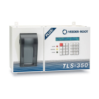
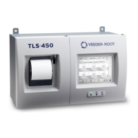
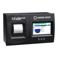
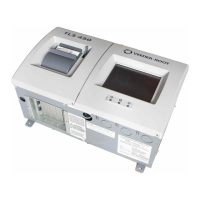
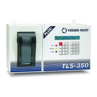
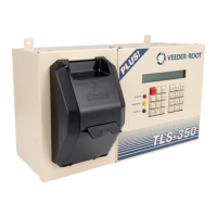
Figure 2-2. Typical TLS-IB Installation
tlsnt\tlsibmnt.eps
1000 mm
(Maximum)
1500 mm
(Maximum)
One 5 ampere fused,
switched, neon indication
spur (for 240 Vac), or a
dedicated circuit breaker
rated for 15 amperes, 120 Vac
or 240 Vac. NOTE, circuit breaker
must be marked as the power
disconnect for the TLS-IB Console.
IFSF cable
(Optional)
Conduit for probe
field cables
Alternative knockouts
for cable entries
 Loading...

