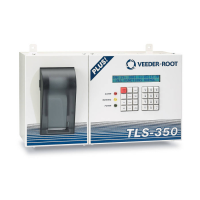
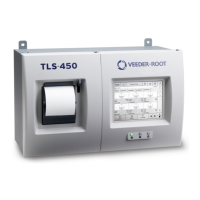
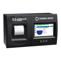
Wiring/Miscellaneous For TLS-IB Consoles W/RS-232 & With & W/O IFSF) TLS-IB Specifications
4-15
• Veeder-Root RS-232 command protocol format applies. Table 4-3 lists serial commands recognized by the TLS-
IB:
SIGNAL INPUT SPECIFICATIONS
• Up to 8 Veeder-Root Magnetostrictive probes can be monitored.
• Probe data: 0.2 A at 13 volts.
Table 4-2. TLS-IB Serial Interface Connections
J7 Connections Computer Terminal (DB-25 Connector)
A (receive) TXD (pin 2)
B (transmit) RXD (pin 3)
G (signal ground) GND (pin 7)
Table 4-3. TLS-IB Serial Commands
Command Description
001 System Reset
002 Clear Power Reset Flag
003 Remote Alarm Reset
201
In-Tank Inventory Report (height, water, and temp
only)
205 In-Tank Status Report
517 Set System Type & Language Flags (ext. lang. set)
601 Set Tank Configuration
62F Set Mag Probe Float Size
881 Set Communication Port Data
882 Initialize Communication Port Data
902 System Revision Level Report
A01 Probe Type and Serial Number
A02 Probe Factory Dry Calibration Values
A10 Probe Last Sample Buffers
A11 Probe Fast Average Buffers
A12 Probe Standard Average Buffers
 Loading...

