23
4Connectingtopowersupply
MINITRAC 31 • Foundation Fieldbus
62076-EN-190704
instructionsarepartofthescopeofdeliveryandcomewiththeEx-
approved instruments.
8
9
2
1
7
5
3
4
6
1
1
24
/L
/N
PE
56
22
11
12
2122 1920 18 17 14 1316 15 12
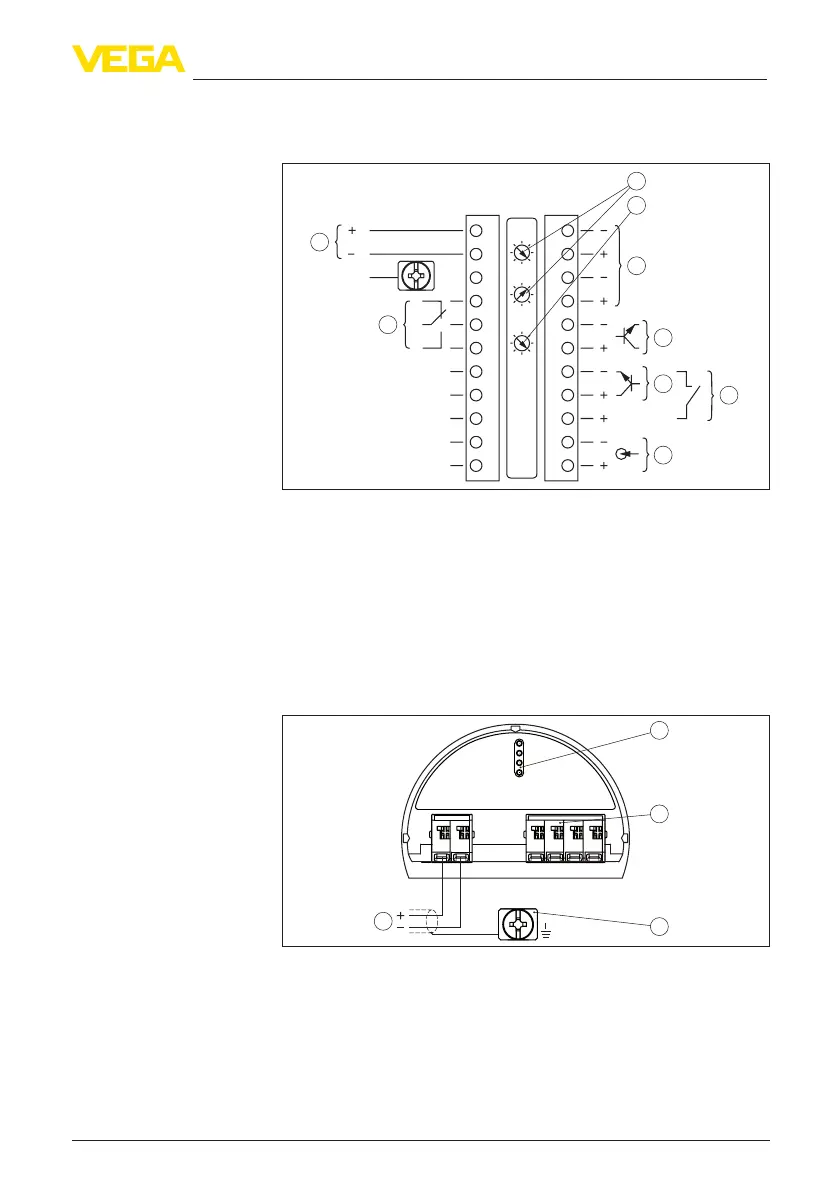
Fig. 16: Electronics and connection compartment (Ex-d) with instruments with
intrinsically safe signal output
1 Voltage supply
2 Relay output
3 Signal input 4 … 20 mA (active sensor)
4 Switching input for NPN transistor
5 Switchinginputoating
6 Transistor output
7 Interface for sensor-sensor communication (MGC)
8 Simulation switch (1 = simulation on)
9 Setting the bus address for sensor-sensor communication (MGC)
4)
567
8
2
3
4
1
2
+
( )
(-)
1
Fig. 17: Adjustment and connection compartment (Ex-ia) with instruments with
intrinsically safe signal output
1 Terminals for intrinsically safe signal output FF bus
2 Contact pins for the display and adjustment module or interface adapter
3 Terminals for the external display and adjustment unit
4 Ground terminal
Electronics and connec-
tion compartment - In-
struments with intrinsi-
cally safe signal output
Adjustment and connec-
tion compartment - In-
struments with intrinsi-
cally safe signal output
4)
MGC = Multi Gauge Communication

 Loading...


