40
11 Applications and functions
VEGAMET 861 • 4 … 20 mA/HART
58866-EN-200401
1
2
3
4
Fig. 16: Example pumping station: Pump control in the inlet shaft
1 VEGAMET 861
2 Radar sensor
3 Pump 1
4 Pump 2
When pump control is activated, the assigned relays and possible
pump malfunctions are also displayed in the status bar of the meas-
ured value indication.
1 2 3 4
1
2
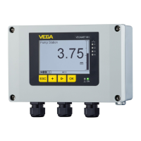
Fig. 17: Status bar in display when pump control is activated
1 Symbol, activated pump control
2 Relay 1 and 2 are assigned to the pump control
3 Relay 3 is assigned to the pump control and signals failure
4 Relay is free i.e. not assigned to the pump control
Setup
An application wizard guides you through the most common selection
possibilities. Further application options are available on the corre-
sponding DTM/app pages. A more detailed description of all available
application options is included in the DTM online help.
The following steps must be carried out in the application wizard:
1. Select application
Display indication
 Loading...