34
5 Connecting to the bus system
VEGAPULS 62 • Probus PA
36505-EN-181127
Information:
Solid cores as well as exible cores with wire end sleeves are insert-
ed directly into the terminal openings. In case of exible cores without
end sleeves, press the terminal from above with a small screwdriver,
the terminal opening is then free. When the screwdriver is released,
the terminal closes again.
You can nd further information on the max. wire cross-section under
"Technical data - Electromechanical data".
7. Check the hold of the wires in the terminals by lightly pulling on
them
8. Connect the screen to the internal ground terminal, connect the
external ground terminal to potential equalisation
9. Tighten the compression nut of the cable entry gland. The seal
ring must completely encircle the cable
10. Reinsert the display and adjustment module, if one was installed
11. Screw the housing lid back on
The electrical connection is nished.
5.3 Wiring plan, single chamber housing
The following illustration applies to the non-Ex as well as to the Ex-ia
version.
5
00
5
1
6
2
7
3
8
4
9
0
5
1
6
2
7
3
8
4
9
1
0
1
678
Bus
3
4
5
1
2
+
( )
(-)
1
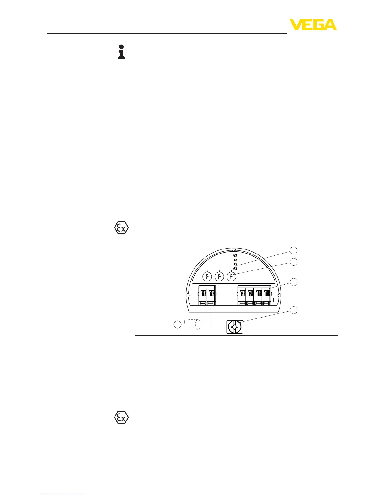
Fig. 24: Electronics and connection compartment - single chamber housing
1 Voltage supply, signal output
2 For display and adjustment module or interface adapter
3 Selection switch for instrument address
4 For external display and adjustment unit
5 Ground terminal for connection of the cable screening
5.4 Wiring plan, double chamber housing
The following illustrations apply to the non-Ex as well as to the Ex-ia
version.
Electronics and connec-
tion compartment

 Loading...