16
Operation
Radar - Level measurement in bulk solids
29427-EN-160312
12 Operation
12.1 Adjustment on the measurement loop
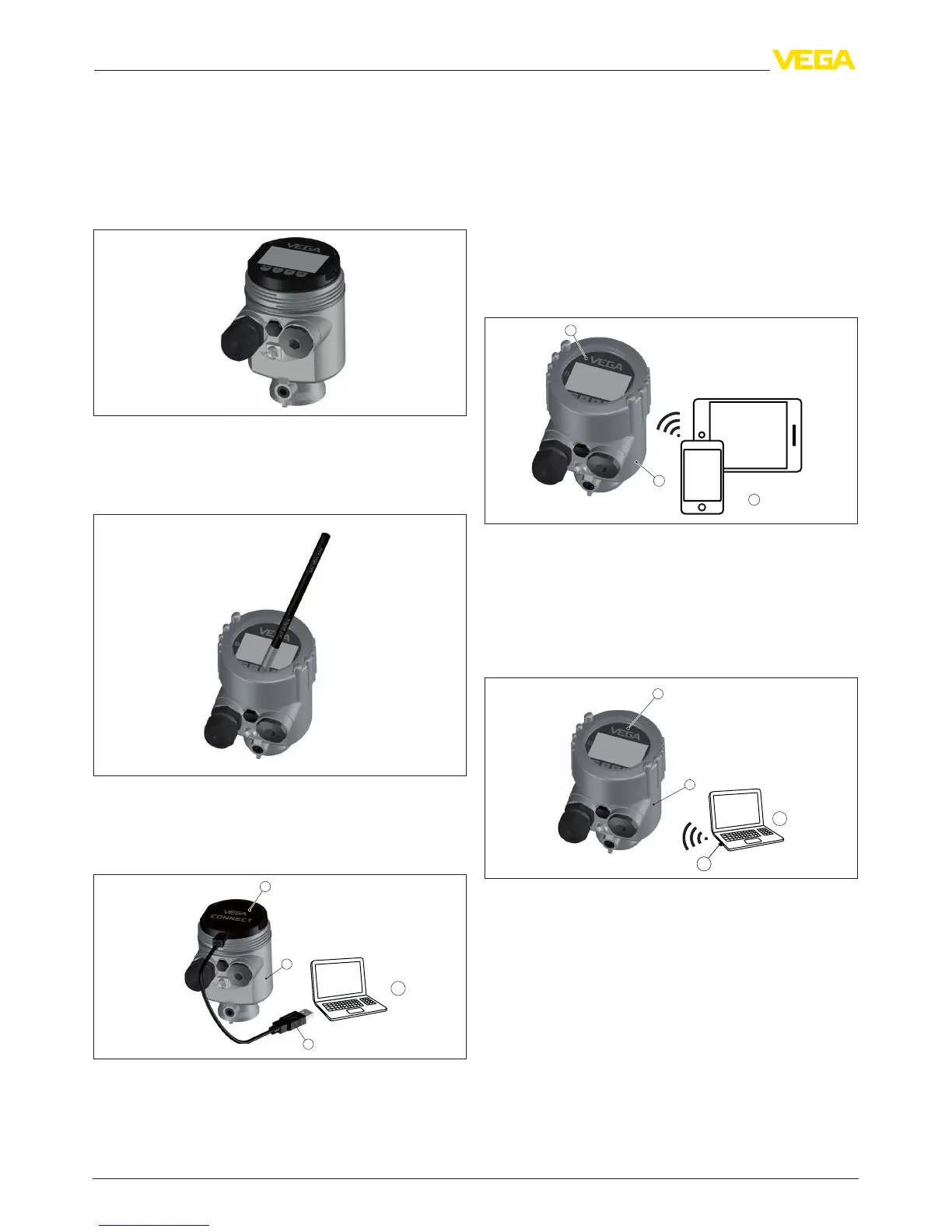
Via the display and adjustment module through keys
The plug-in display and adjustment module is used for measured value
indication, adjustment and diagnosis. It is equipped with an illuminated
full dot matrix as well as four keys for adjustment.
Fig. 28: Display and adjustment module with single chamber housing
Via the display and adjustment module through magnetic pen
With the Bluetooth version of the display and adjustment module, the
sensor can also be adjusted with the magnetic pen. This is done right
through the closed lid (with inspection window) of the sensor housing.
Fig. 29: Display and adjustment module - with adjustment via magnetic pen
Via a PC with PACTware/DTM
The interface converter VEGACONNECT is required for connection of
the PC. The converter is placed on the sensor instead of the display and
adjustment module and connected to the USB interface of the PC.
2
3
1
4
Fig. 30: Connection of the PC via VEGACONNECT and USB
1 VEGACONNECT
2 Sensor
3 USB cable to the PC
4 PC with PACTware/DTM
PACTware is an adjustment software for conguration, parameter adjust-
ment, documentation and diagnosis of eld devices. The corresponding
device drivers are called DTMs.
12.2 Operation in the measurement loop environ-
ment - wireless via Bluetooth
Viaasmartphone/tablet
The display and adjustment module with integrated Bluetooth functional-
ity allows wireless connection to smartphones/tablets with iOS or Android
operating system. The adjustment is carried out via the VEGA Tools app
from the Apple App Store or Google Play Store.
1
2
3
Fig. 31: Wireless connection to smartphones/tables
1 Display and adjustment module
2 Sensor
3 Smartphone/Tablet
Via a PC with PACTware/DTM
The wireless connection from the PC to the sensor is carried out via
the Bluetooth USB adapter and a display and adjustment module with
integrated Bluetooth function. The adjustment is carried out via the PC
with PACtware/DTM.
2
1
4
3
Fig. 32: Connection of the PC via Bluetooth adapter
1 Display and adjustment module
2 Sensor
3 Bluetooth USB adapter
4 PC with PACTware/DTM
12.3 Adjustment carried out at position remote from
the measuring point - wired
Via external display and adjustment units
For this, the external display and adjustment units VEGADIS 81 and 82
are available. The adjustment is carried out via the keys of the built-in
display and adjustment module.
The VEGADIS 81 is mounted at a distance of 50 m from the sensor and
directly to the sensor electronics. VEGADIS 82 is looped directly into the
signal cable at any point.

 Loading...


