3
.
www.velodyne.com
HDL-64E User’s Manual
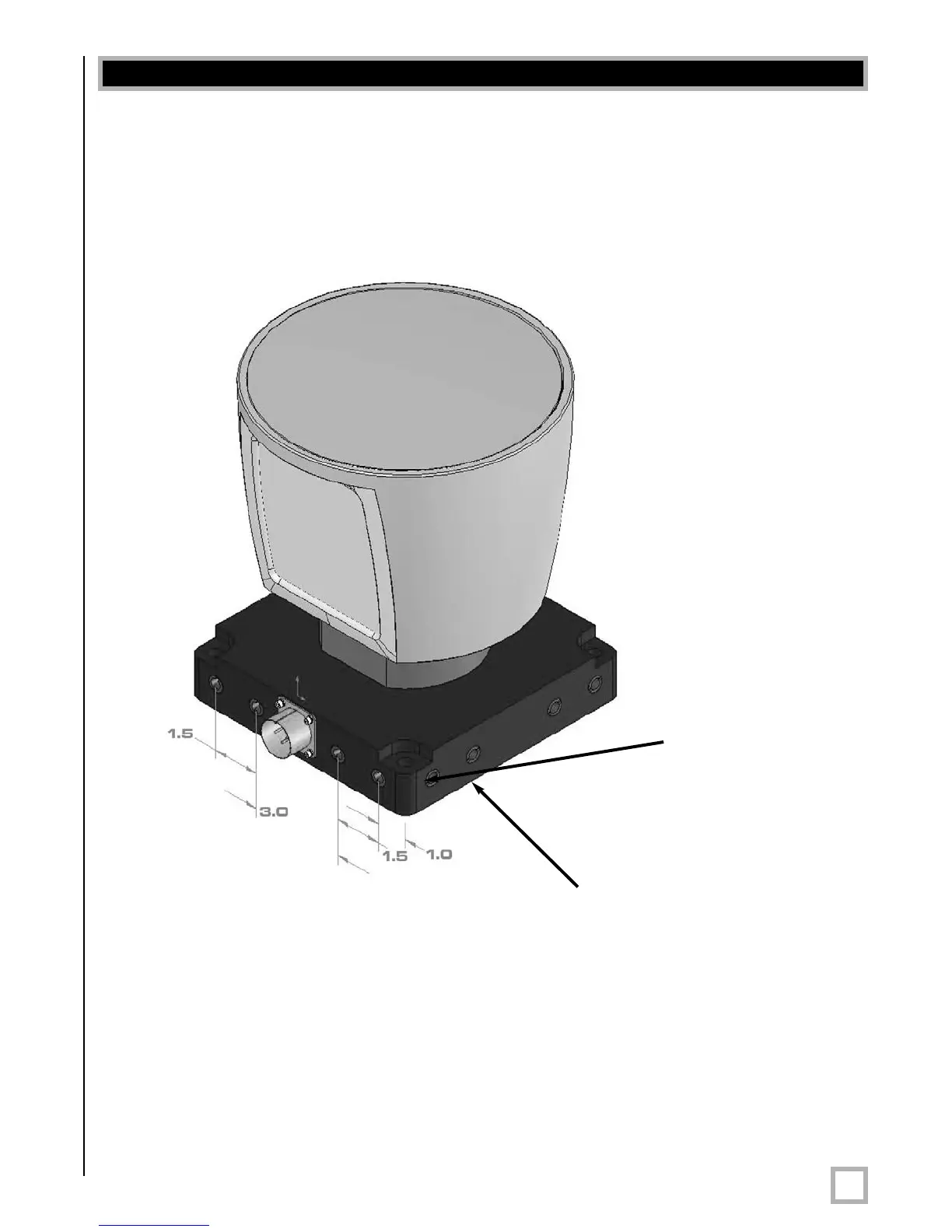
Front/Back Mounting
The HDL-64E base provides two mounting options: side mount and top mount. See Figure 2
for front/back mounting options, Figure 3 for side/side mounting, and Figure 4 for top
mounting instructions.
Figur
e 2
. Front and back HDL mounting illustration.
See Figure 2. This figure shows the HDL-64E’s base plate screw locations with threaded inserts
for standard M8 hardware.
Installation Overview
Four M8-1.25 x 12mm
deep mounting points.
(Four per side, for a
total of 16.)
Mounting
Base
 Loading...