5
.
www.velodyne.com
HDL-64E User’s Manual
Top Mounting
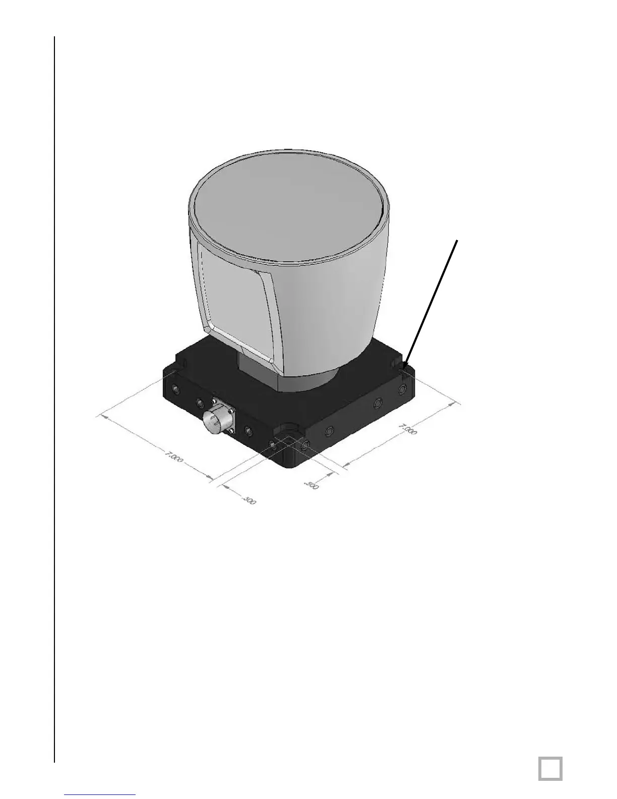
Figure 4. HDL top mounting illustration.
Figure 4 shows the location of four .406” thru holes for top mounting.
For all mounting options, be sur
e the HDL-64E is mounted secur
ely to withstand vibration and
shock without risk of detachment. The unit need not be shock proofed — it is designed to
withstand standar
d automotive G-for
ces.
The HDL-64E is weatherpr
oofed to withstand wind, rain, and other adverse weather conditions.
The spinning nature of the HDL-64E helps the unit shed excess water from the front window
that could hamper performance.
Four .406” through
holes for top mount
option to secure the
HDL to the vehicle.
 Loading...