11 VELUX
®
$-+061:+0-6.795);176
"' (-6;9)4-
$?8(
#;)6,)9,6:+04<::84)6
*D1>4 ?3 *59D5F?> 1>42E38- +538>9;
!++175C<938D).=2.59458?BCDU<<8?BCD+5>75B>+5<56?>+5<561H
U<D97F?=EC712541DE=29CJEB%5E1E6<175595D19<<TCE>75>21E@8IC9;1<9C385>>7125>'B?4E;D ?45B$1D5B91<25C38B592E>75>C9>4D538>9C385N>45BE>75>F?B2581<D5>
95C5,>D5B<175/5938>E>79CDEB8525BB538D<93875C38UDJDE>4E>D5B<957D;59>5=N>45BE>7C495>CD5B=@6S>75B41B6C95>EBJE45=/G53;25>EDJ5>JE45=C9598=1>F5BDB1EDGEB45
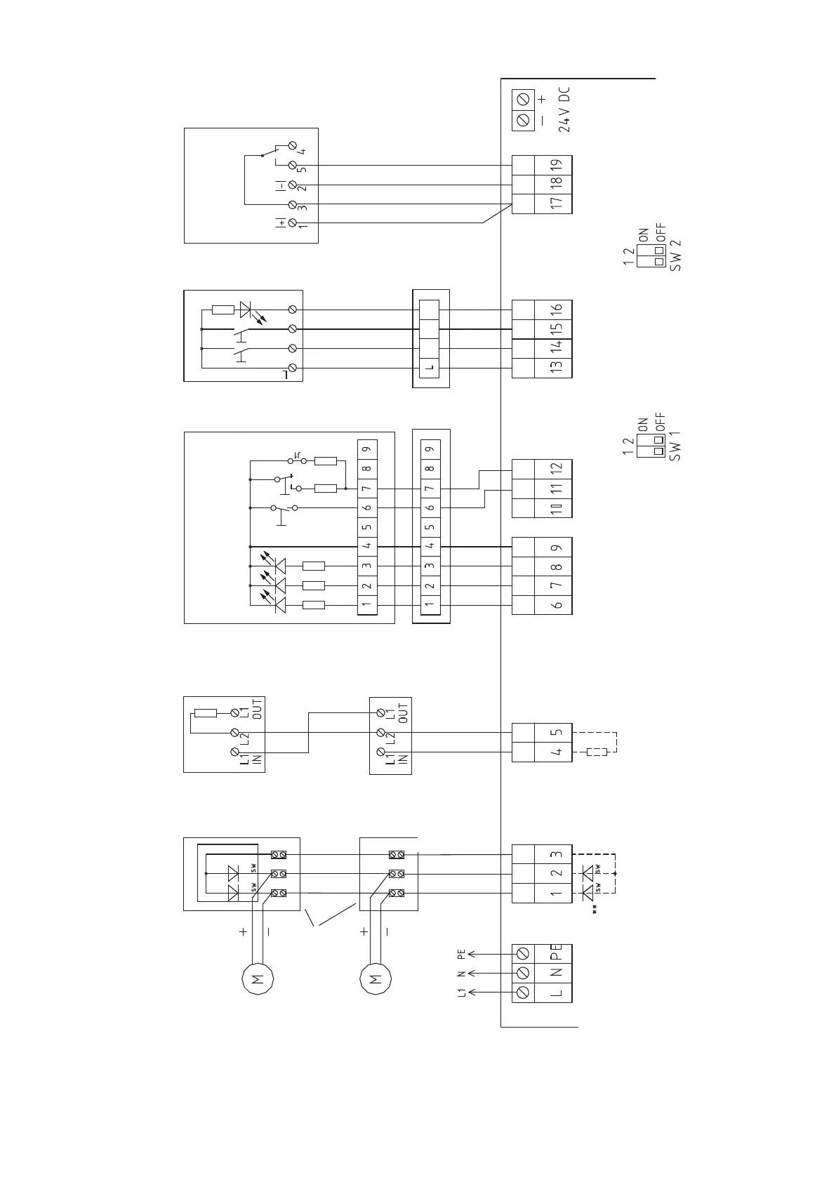
Potential-free
contact
Last ventilation switch
Wind/rain sensors
Type: W+RE 24 V/2
Ventilation
switches
Break-glass points
HAT 01
Power
230 V /50 Hz .... VA
Detectors
RM S65
Motors
Connection diagram for control unit KFC 100J
Last break-glass point Last automatic detector
Last motor
Junction box
Monitoring
First motor
First automatic
detector
First break-glass
point
First ventilation
switch
*Terminal
module
OPEN
OPEN
OPEN
Jumper
Note: Jumper J1 must be inserted in the last
or only break-glass point!
CLOSE
CLOSE
CLOSE
Indicator-OPEN
Alarm
Alarm
Motor term. module
Only insert terminal mod-
ule in the last or only
detector!
Only insert the motor ter-
minal module in the last or
only motor!
Note: If motors operate in the
wrong direction, transpose the
+ and - wires of the motor cable.
Note:
Strip the power supply cable (max 2 cm) or connect the connection
cables directly to the printed circuit board connector with a cable tie so
that if a connection cable is loosened, it cannot touch the neighbouring
terminals or metal parts of the housing.
* If smoke detectors are connected, the terminal module must be removed
from terminals 4 and 5 and inserted in the last or only smoke detector.
Only connect the terminal module here if there are not any smoke detectors
connected.
CLOSE
Error
Operation
Terminal
module
Break-glass point
gn
gn yel red
red
blue
grey
red
blue
grey
** Motor terminal module in
factory setting (for trans-
portation only!)
Mains Motors Smoke detectors Break-glass points Ventilation
switches
Wind/rain sensors
Standard connection diagram
Indicator

 Loading...