12 VELUX
®
$-+061:+0-6.795);176
"' (-6;9)4-
$?8(
6:+04<::84)651;.G9
*D1>4 ?3 *59D5F?> 1>42E38- +538>9;
!++175C<938D).=2.59458?BCDU<<8?BCD+5>75B>+5<56?>+5<561H
U<D97F?=EC712541DE=29CJEB%5E1E6<175595D19<<TCE>75>21E@8IC9;1<9C385>>7125>'B?4E;D ?45B$1D5B91<25C38B592E>75>C9>4D538>9C385N>45BE>75>F?B2581<D5>
95C5,>D5B<175/5938>E>79CDEB8525BB538D<93875C38UDJDE>4E>D5B<957D;59>5=N>45BE>7C495>CD5B=@6S>75B41B6C95>EBJE45=/G53;25>EDJ5>JE45=C9598=1>F5BDB1EDGEB45
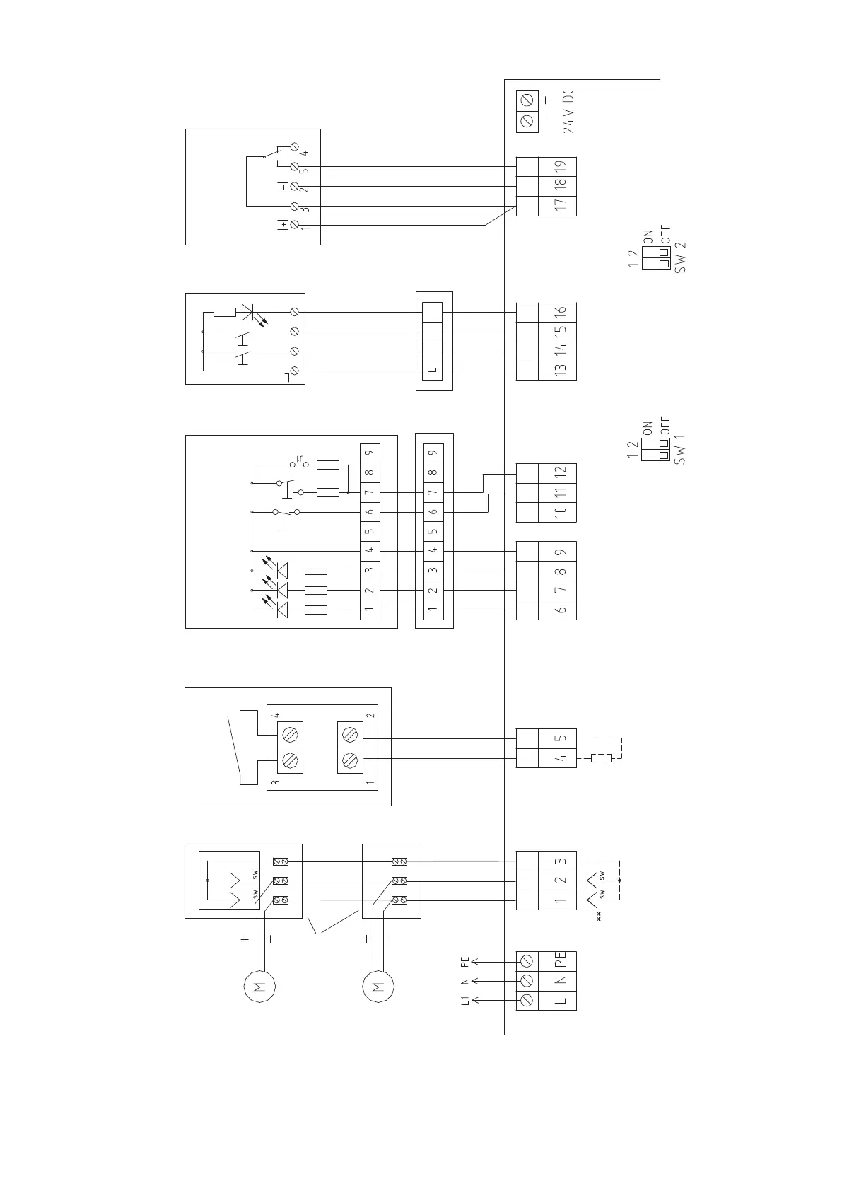
Fire alarm system
(remote alarm)
blue
Potential-free
alarm contact
(normally open
contact)
Smoke detectors
FAM
red
*Terminal
module
Potential-free
contact
Last ventilation switch
Wind/rain detector
Type: W+RE 24V /2
Ventilation switchesBreak-glass points
HAT 01
Power
230 V/50 Hz/ .... VA
Motors
Connection diagram for control unit KFC 100J with external alarm module (FAM)
Last break-glass point
Last motor
Junction box
Monitoring
Last motor
First break-glass
point
First ventilation
switch
OPEN
OPEN
OPEN
Jumper
Note: Jumper J1 must be inserted in the last
or only break-glass point!
CLOSE
CLOSE
CLOSE
Indicator-OPEN
Alarm
Alarm
Motor term. module
Only insert the motor ter-
minal module in the last or
only motor!
Note: If motors operate in the
wrong direction, transpose the
+ and - wires of the motor cable
Note:
Strip the power supply cable (max 2 cm) or connect the connection
cables directly to the printed circuit board connector with a cable tie so
that if a connection cable is loosened, it cannot touch the neighbouring
terminals or metal parts of the housing.
* If the fire alarm system module is connected, the terminal module must be
removed from terminals 4 and 5, and the fire alarm system module must be
inserted in the control unit of the fire alarm system instead.
Only connect the terminal module here if there is not any fire alarm system
module connected.
CLOSE
Error
Operation
Break-glass point
Indicator
gn
gn yel red
grey
grey
** Motor terminal module in
factory setting (for trans-
portation only)
Mains Motors Break-glass points Ventilation
switches
Wind/rain sensors
Connection diagram with external alarm module (FAM) for fire alarm systems
 Loading...