6
2. CONTROLS
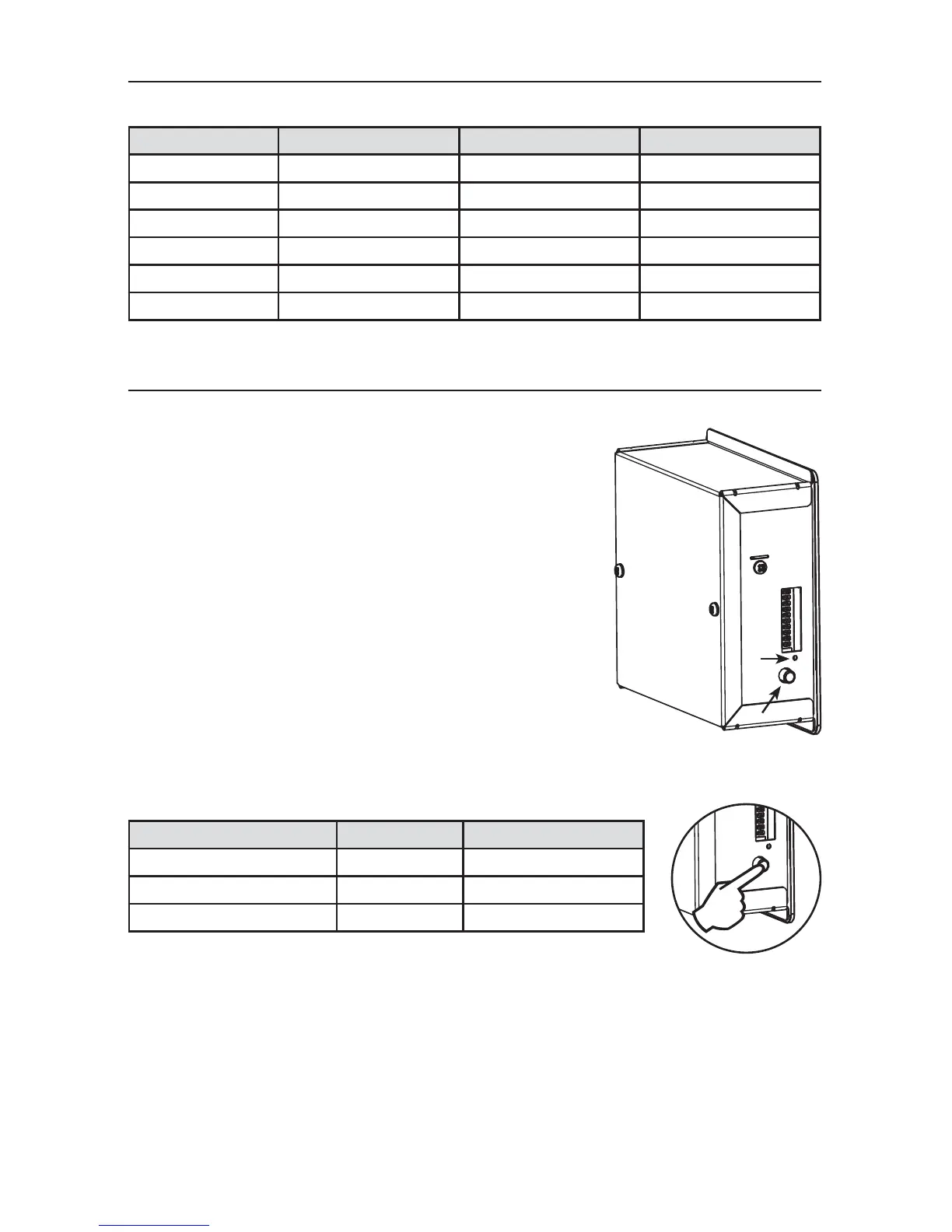
These units are equipped with an integrated control, located on the
electrical compartment. Use the push-button (1) to control the unit.
The LED (2) will then show on which mode the unit is in.
NOTES: 1. The integrated control must be turned OFF to use an
optional main control.
2. If an optional auxiliary control is used, if activated, this
auxiliary control will override the optional main control.
2.1 INTEGRATED CONTROL
VD0278
1
2
VD0281
Refer to table below to see how to operate the unit using its integrated control.
PRESS ON PUSH-BUTTON LED COLOR RESULTS
ONCE AMBER UNIT IS ON LOW SPEED
TWICE GREEN UNIT IS ON HIGH SPEED
THREE TIMES NO LIGHT UNIT IS OFF
2.1.1 BOOT SEQUENCE
The unit boot sequence is similar to a personnal computer boot sequence. Each time the unit
is plugged after being unplugged, or after a power failure, the unit will perform a 30-second
booting sequence before starting to operate. During the booting sequence, the integrated
control LED will light GREEN or AMBER for 5 seconds, and then will shut off for 2 seconds.
After that, the LED will light RED for the rest of the booting sequence. During this RED light
phase, the unit is checking and resetting the motorized damper position. Once the motorized
damper position completely set, the RED light turns off and the booting sequence is done.
NOTE: No command will be taken until the unit is fully booted.
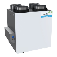
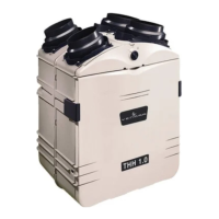
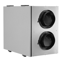
MODEL HRV CONSTRUCTO 1.5ES HRV CONSTRUCTO 2.0ES ERV CONSTRUCTO 2.0ES
W
IDTH 30¼" 30¼" 34"
H
EIGHT 16½" 16½" 16½"
D
EPTH 17
1
∕8" 17
1
∕8" 17
1
∕8"
WEIGHT 65 LB (29.5 KG) 65 LB (29.5 KG) 76 LB (34.5 KG)
ELECTRICAL SUPPLY 120 V, 60 HZ 120 V, 60 HZ 120 V, 60 HZ
POWER CONSUMPTION 160 WATTS 195 WATTS 200 WATTS
1.5 SPECIFICATIONS
1. YOUR UNIT AND ITS PURPOSE (CONT’D)
 Loading...