16
For the Installer
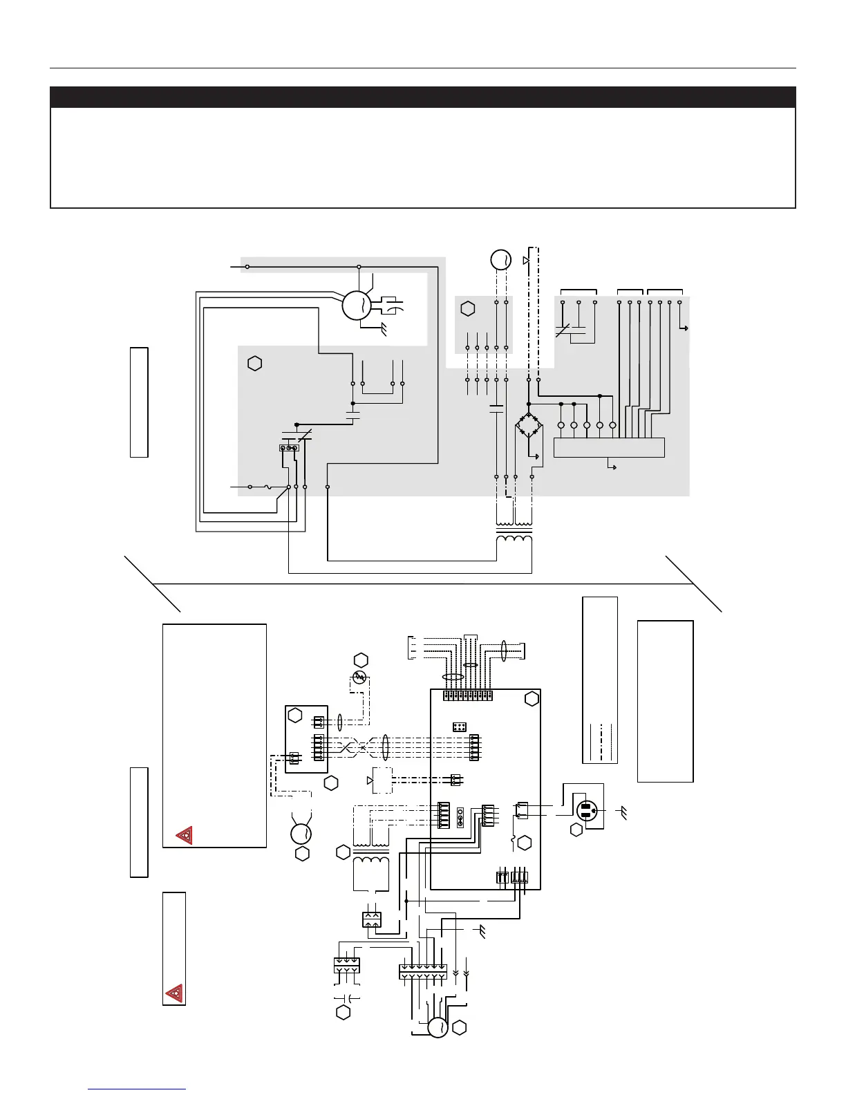
11. WIRING DIAGRAM
Field wiring
remote control
(see notes 3 & 4)
120 V, 60 Hz
W1
J6
J4
ELECTRONIC
ASSEMBLY
1
2
1
2
3
1234
12
12345
12345
J8
J9
J11
J10
12
J12
J13
J14
10
9
8
7
6
5
4
3
2
1
B
24 V
class 2
9.5 V
class 2
120V, 60Hz
Neutral
120 V, 60Hz
Line
CPU
K2
K4
K5
J10-2
Line voltage factory wiring
Class 2 low voltage factory wiring
Class 2 low voltage field wiring
See note 1
120 V
Door interlock switch
(magnetically actuated
1234512
12
J3
J2
J1
t˚
Damper motor
BK
Override
switch
Furnace blower interlock
J14-1 : NO
J14-2 : COM
J14-3 : nc
(optional; see notes 3, 5)
DAMPER
ELECTRONIC ASSEMBLY
Defrost
temperature sensor
WIRING DIAGRAM
LOGIC DIAGRAM
J4-1
J4-3
J6-2
J6-1
K3
K2
24 V
class 2
9.5 V
class 2
120 V
J9-1
J9-2
J9-3
J4-2
J9-4
J8-1
J8-2
J8-4
J8-5
K4
J12-2
J12-1
A1
Damper motor
J3-2
J3-1
J2-2
J2-1
F1
J12-5
J12-4
J12-3
J2-3
J2-4
J2-5
Door interlock switch
J11-2
J11-1
K1
K3
K5
J14-3
J14-1
J14-2
Furnace
blower
interlock
(optional; see
notes 3, 5)
J14-4
J14-5
J14-6
J14-7
J14-8
J14-9
J14-10
Override
switch
(optional; see
notes 3, 4)
Field wiring
remote
control (see
notes 3, 4)
ICP
BK
YRG
W W
nc
Motor
capacitor
Fan
motor
GN
GN
BN
BN
Y
Y
BK
W
A2
A2
M3
T1
S1
R1
A1
F1
M1
(optional; see
notes 3 & 4)
VE0257A
COLOR CODE
BK BLACK
BL BLUE
BN BROWN
GY GRAY
GN GREEN
Critical characteristic.
reed switch)
JU1
3
2
1
NOTES
1. For continued fire protection. Use specified
UL listed/CSA Certified line fuse (3A, 3AG Type).
2. If any of the original wire, as supplied, must
be replaced, use the same equivalent wire.
3. Field wiring must comply with applicable
codes, ordinances and regulations.
4. Remote controls (class 2 circuit) available,
see instruction manual.
5. Furnace fan circuit must be class 2 circuit only.
J10-1
nc
nc
nc
nc
2
21
1
BK
BK
W
W
C1
2
21
1
3
3
BK
BK
nc
2
21
1
3
3
4
4
5
5
6
6
ncnc
BN
BN
GN
GND
HI
COM
LO
MED
O
O ORANGE
RRED
W WHITE
Y YELLOW
nc no connection
GY
R
BL
nc
BK
BK
O
GY
R
BN
BN
nc
nc
JU1
HM
213
Fan
motor capacitor
COM
HI
LOW
MED
HI
LOW
Fan
motor
⚠WARNING
• Risk of electric shocks. Before performing any maintenance or servicing, always disconnect the unit from its power
source.
• This product is equipped with an overload protection (fuse). A blown fuse indicates an overload or a short-circuit situation.
If the fuse blows, unplug the product and check the polarity and voltage output from the outlet. Replace the fuse as per the
servicing instructions (refer to wiring diagram for proper fuse rating) and verify the product. If the replaced fuse blows, it may
be a short-circuit and the product must be discarded or returned to an authorized service center for examination and/or repair.