11
For the Installer
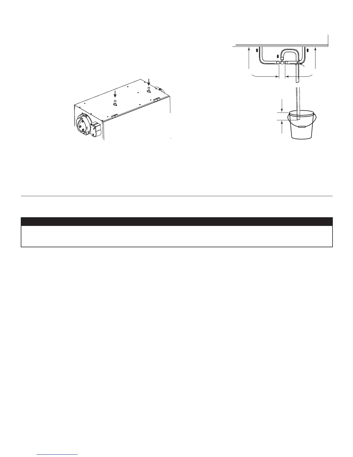
6.6 CONNECTING THE DRAIN
1. Cut 2 sections of plastic tubing of at least 12” each.
2. Connect each one of them to the inner drain fittings located under the unit.
3. Join their other ends to the "T" junction and remaining tubing as illustrated. This will
prevent the unit from drawing unpleasant odors from the drain source.
FOR HRV SOLO 1.5ES AND HRV SOLO 2.0ES UNITS ONLY:
4. Insert both drain plugs (included in parts bag) in the alternate drain fittings located on
top of the unit.
VD0282
VD0325A
12” minimum 12” minimum
TIE WRAP
7. CONTROLS
7.1 SETTING EXTENDED DEFROST
These units are factory set to normal defrost. In cold areas, it may be necessary to setup extended defrost. To do so, during the first
5seconds of the booting sequence, while the integrated control LED is GREEN, press on the integrated push button (about 3 seconds)
until the LED turns AMBER.
CAUTION
For HRV Solo 1.5ES and HRV SOLO2.0ES units only: when installed in reverse postion (upside down) in a cold
area where outside temperature could drop below -20C (-4F) for more than 5 days in a row, the unit must always
be set in extended defrost.