6
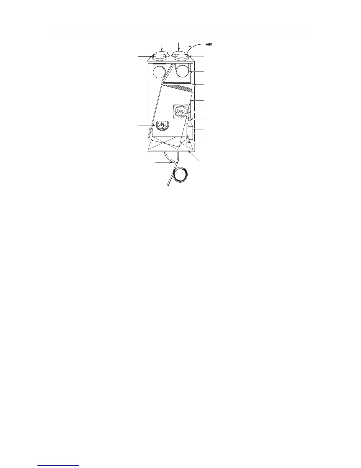
1 Stale air intake port: is connected to the registers located in the larger rooms of
the house.
2 Fresh air port: brings fresh air from the outdoors into the unit.
3 Exhaust port: exhausts stale air to the outdoors, after the air has transferred
its heat inside the heat recovery core.
4 Distribution port: distributes fresh air into the house, after it has absorbed the
heat of the stale air in the heat recovery core.
5 Mechanical filters: trap the dust contained in the air and prevent the heat recovery
core from becoming obstructed.
6 Heat recovery core: is a counterflow type. It transfers the heat between the two air
streams.
7 Blowers: draw fresh air from outdoors and exhaust stale air to
outdoors. The blower wheels are driven by two motors.
8 Capacitor: is indispensable to proper motor operation.
9 Condensation tray: is used to capture the water produced during heat transfer and
defrost (in cold climate).
10 Drainage tube: is connected to the condensation tray and serves to drain the
water within.
11 Electronic circuit: located inside the electrical box, insures proper operation of
the unit.
12 Automatic defrost unit: consists of one damper actuator, dampers and related
controls. The defrost cycle is electronically controlled in
response to the outdoor temperature (-5°C [23°F] to -40°C
[-40°F]) and will increase in frequency as the temperature
decreases. Its duration is of 5 or 6 minutes according to models.
13 Control connector: located inside the electrical box, allows to connect the main
and auxiliary controls.
14 Electrical cord: for 120 V electrical supply.
3. DESCRIPTION OF THE UNIT
1
2
3
4
5
5
6
7
7
8
9
10
11
12
13
14
VL0012