Page 14
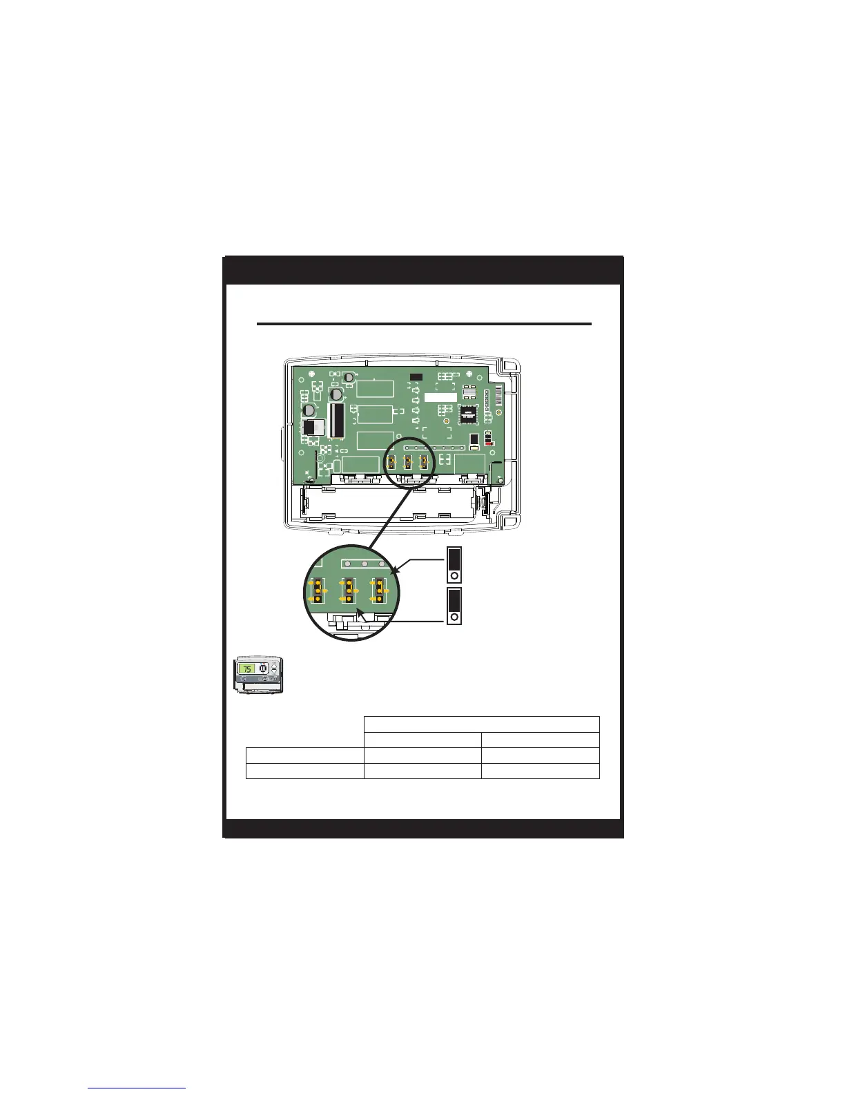
Jumper Configuration
*Output active depending on O/B jumper configuration - For normal
operation do not connect to equipment.
OUTPUTS
No Demand With Demand
Cooling Mode
Heating Mode
O/B*
Y, G, O/B*
O/B*
W, O/B*
Cooling and Gas Heating
Residential Gas, Electric Cool, split systems & package units.
Jumper #1 (J1) should be set for GAS and
Jumper #2 (J2) should be set for GAS/ELEC for
for typical gas furnace heating with electric
cooling. Jumper #3 (J3) is not used.
INSTALLATION INSTRUCTIONS
T1035
GAS
GAS/ELEC
J1
J2
PCB: 00597 Rev. AA
PCA: 00569 Rev.
O
B
GAS/ELEC
HP
GAS
ELEC/HP
BAT+
BAT-
1000
JFK
SKD
1000
JFK
SKD
1000
JFK
SKD
MODEL: T1035
082100009
C
RH
Y
W
G
RC
O/B
471
471
471
R16
R18
C11
D7
NNE ACPJA
P4S220-5
N8 3D4
471471
471471
O
B
GAS/ELEC
HP
GAS
ELEC/HP
C
RH
Y
J1J2J3
J1J2J3
Su
PM
I2:00
:
 Loading...