EasyManua.ls Logo

Venstar T1070 User Manual

Venstar T1070
30 pages
To Next Page IconTo Next Page
Page #1 background imageLoading...
Page #1 background image
VENSTAR
FAN COIL
THERMOSTAT
FAN COIL
THERMOSTAT
T1070
NON-
PROGRAMMABLE
2 OR 4 PIPE
SYSTEMS
OWNER’S MANUAL
AND
INSTALLATION INSTRUCTIONS
Remote sensor ready
3 speed fan control
Self-prompting adjustment
Auto 2-pipe changeover
when used with ACC-SENFC
changeover sensor
Dry contact equipped
Backlit display
Works with most fan
coil systems - 24vac
Electric heat ready
Non-volatile memory
Dual setpoint with
adjustable deadband
Keypad lockout
Configurable display
Display F or C
Question and Answer IconNeed help?

Do you have a question about the Venstar T1070 and is the answer not in the manual?

Venstar T1070 Specifications

General IconGeneral
DisplayColor touchscreen
Wi-FiYes
Programmability7-day programmable
ConnectivityWi-Fi
Battery BackupYes (AA Batteries)
Weight0.5 lbs
Power Source24VAC or Battery
Temperature Range40°F to 99°F
FeaturesRemote Access

Summary

Front Panel Components

Liquid Crystal Display

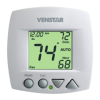
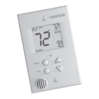
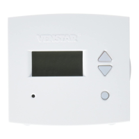
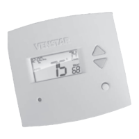
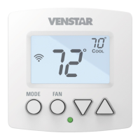
Displays current temperature, mode, and setpoint.

Mode Selection Button

Selects operational modes: Heat, Cool, Auto, Off.

Display Elements and Icons

Selecting Operating Modes (4-Pipe)

Automatic Heat/Cool Switching

Enables automatic switching between heating and cooling modes.

Selecting Operating Modes (2-Pipe)

Selecting Operating Modes (2-Pipe Continued)

Selecting Operating Modes (2-Pipe with Sensor)

2-Pipe Auto Heat/Cool with Sensor

For systems with sensors or specific advanced configurations.

Basic Thermostat Operations

Setting Desired Temperature

Adjusts heating and cooling setpoints.

Advanced Setup: Initial Configuration

Advanced Setup: System Type Configuration

Fan Coil System Type Selection

Chooses between 2-pipe and 4-pipe fan coil systems.

2-Pipe System Operation Modes

Defines specific operation modes for 2-pipe systems.

Advanced Setup: Fan and Display Settings

Advanced Setup: Temperature and Sensor Settings

Advanced Setup: Unoccupied Period Settings

Dry Contact Unoccupied Operation Mode

Configures unoccupied mode via dry contact.

Advanced Setup Configuration Summary

Advanced Setups Configuration Table

Comprehensive table of setup steps, ranges, and defaults.

Advanced Features and Operation

Deadband Operation Explained

Controls fan stages based on setpoints and deadbands.

Dry Contact Switch Functionality

Enables external devices to enforce unoccupied mode.

Factory Defaults Reset Procedure

Instructions to restore all settings to factory defaults.

Fan Coil Type Configuration Details

Configures G, G2, G3 outputs for specific fan speeds.

Sample Wiring Diagrams

2-Pipe System Wiring Diagram

Diagram for a 2-pipe system with H2O changeover sensor.

4-Pipe System Wiring Diagram

Diagram for a 4-pipe system with sensors and dry contact.

Duct Sensor Connection Diagram

Specific connection diagram for duct sensor to thermostat.

Auxiliary Input and Phasing Problems

Addresses phasing issues with multiple unit control.

Warranty Information

Related product manuals