Page 9
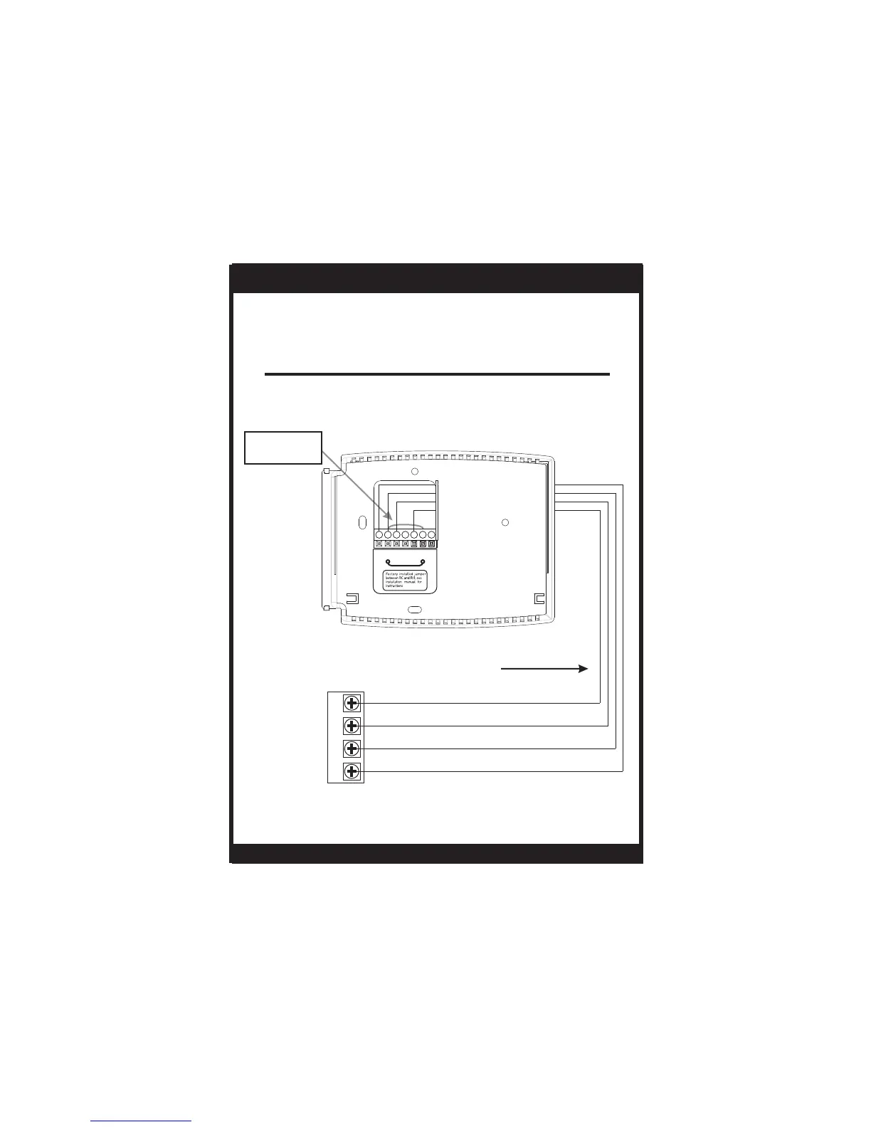
Sample Wiring Diagrams
Gas or Electric Heat
4 Wire, 1 Stage Cooling, 1 Stage Heating-Heat Pump with O reversing valve.
Residential Heat Pumps, split systems & package units, with no auxiliary heat.
For jumper configuration see page 16.
Common wire is optional in all installations. If a common wire is not used the
thermostat must be powered by two AA alkaline batteries. These batteries
must be replaced (page 6) each year or when the Low Battery indicator is
displayed (page 3).
*
INSTALLATION INSTRUCTIONS
T1035
FAN
G
POWER
RO
REVERSING VALVE
COMPRESSOR
Y
4 Conductor 18 to 22 gauge
unshielded cable from the
thermostat to the equipment.
Factory installed
jumper between
RC and RH
CRHYWGRC
O/B
Common wire optional
*
 Loading...