B: Low voltage connections
For best performance use 4-core, low voltage, twisted pair, telecoms type cable for accessories.
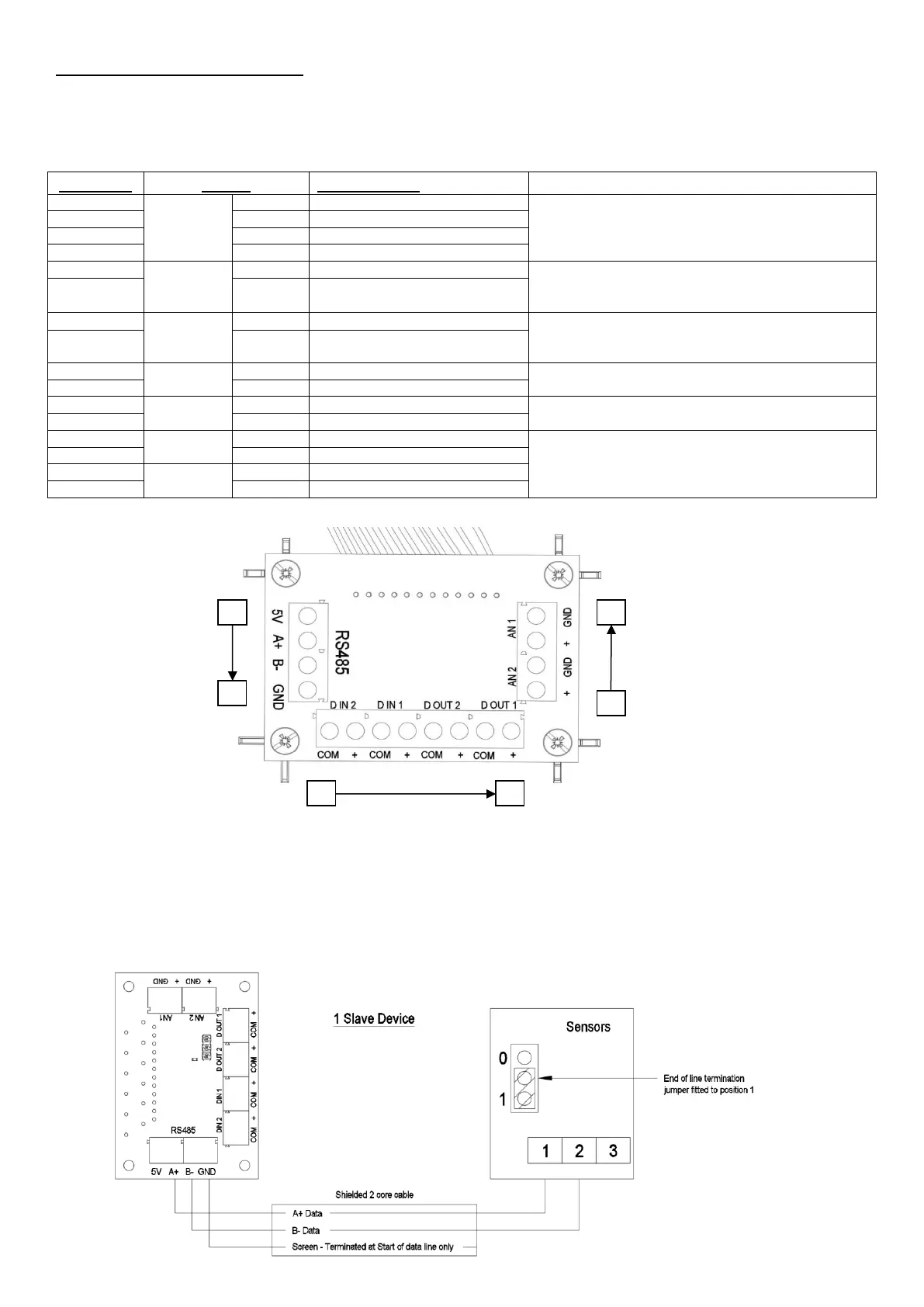
Figure 12
RS485 communication to wired accessories.
Data connection (B, C) if available.
The 5V and Ground connections are available on all units.
Go to Boost speed (Min.1V, max. 6V).
The 5V output from the RS485 connection can be used as
a power supply
Go to Low speed (Min.1V, max. 6V).
The 5V output from the RS485 connection can be used as
a power supply
Unpowered Boost indicator Switch
(switching 6V 50mA max)
Unpowered LED fault indicator switch
(switching 6V 50mA max)
0-10V analogue input.
Two user settable voltage thresholds with two user settable
actions. The unit will run at Normal when supplied voltage is
between the two thresholds.
RS485 Wired inputs
The RS485 terminals are used to connect compatible sensors and switches.
The connection allows sensors be daisy chained to simplify wiring. The maximum length of cable run from
the unit is limited to 250m. Once accessories are wired to the unit, they must be paired to the unit to
function correctly.
RS485 Wired input connection diagram