Low Voltage Venlator Controller
Forced-air System
R
G
B
W
G
R
B G R
R W B G
To Casing
Screw
for Ground
R W B G
Jumper
JP-4*
2 Relays
1 Relay
LVC Version 1
LVC Version 2
Jumper
JP-4*
CONTROLS / WIRING
WWW.CLEANCOMFORT.COM
11
IO-VENT-SS
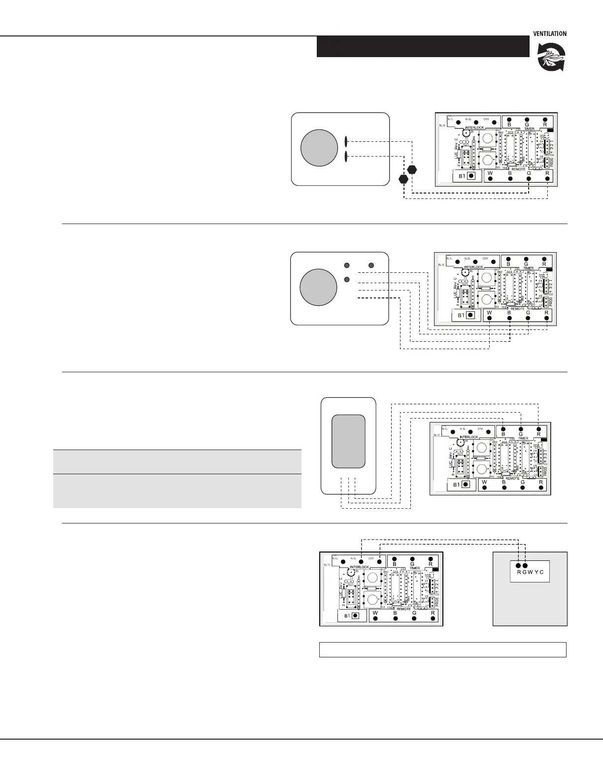
Standard Forced-air Interlocking Wiring
A relay is normally used when tying a venlaon system into
the forced-air distribuon system. The low voltage venlator
control on the venlator is equipped with an internal relay
that will acvate the forced-air system's venlator when
there is a demand from the HRV /ERV.
This venlator control will acvate the INTERLOCK relay
during the following modes: Connuous, Override,
Recirculaon and Defrost. See wiring diagram at right.
Wiring Diagrams for Furnace
Interlock Systems
VHP-T3 TIMER (3 wires)
This control will operate the venlator on high speed
for the length of me (20, 40 or 60 minutes) selected
by the user.
i
CAUTION!
Minimum wire requirement is LVT18 CSA/UL 4 strand to
ensure proper connecon.
Low Voltage Venlator Controller
Legend: -------- Field Installed Low Voltage
Figure 18 Standard forced-air wiring diagram
R
G
B
W
G
R
B G R
R W B G
To Casing
Screw
for Ground
R W B G
Jumper
JP-4*
2 Relays
1 Relay
LVC Version 1
LVC Version 2
Jumper
JP-4*
R
G
B
W
G
R
B G R
R W B G
To Casing
Screw
for Ground
R W B G
Jumper
JP-4*
2 Relays
1 Relay
LVC Version 1
LVC Version 2
Jumper
JP-4*
VHP-RD3P
(4 wires)
This control will operate the venlator when the
relave humidity level measured at the control is
higher than the seng on the control. It can also
override the control on the venlator by reducing
maximum fan speed by 30% on CONT seng and
15% on High (Override) speed.
Controls Connection
Wiring connecons are shown for the Clean Comfort
VHP Series wall controls and mer. See Sequence of
Operaons table for descripon of operaon of these
wall controls and mer with the venlator.
VHP-RD1 (2 wires)
This control will operate the venlator when the rela-
ve humidity level measured at the control is higher
than the seng on the control.
Low Voltage Venlator Controller
Low Voltage Venlator Controller