VENTILATION REQUIREMENTS
WWW.CLEANCOMFORT.COM
12
IO-VENT-SS
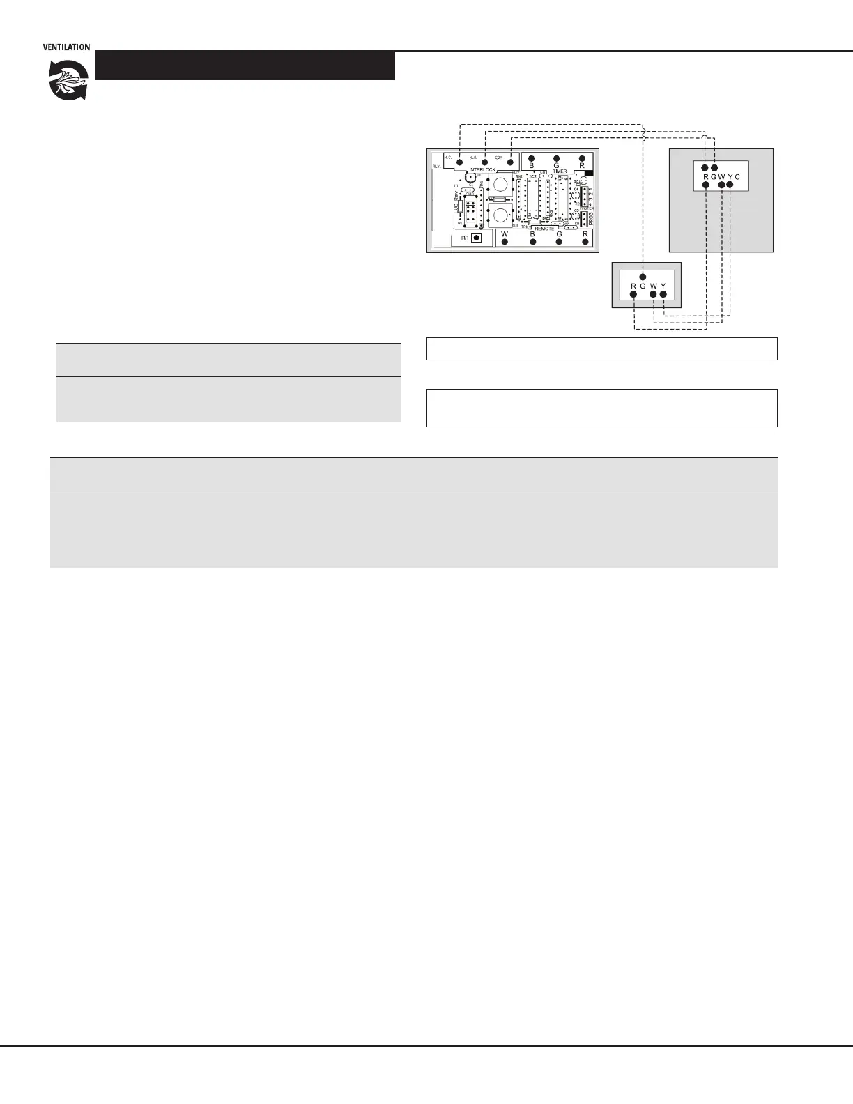
Alternate Forced-Air Interlock Wiring
Some thermostats will acvate the cooling system
when used with the Standard Forced-Air Interlock
Wiring.
If your thermostat operates this way, you must use the
Alternate Forced-Air Wiring shown at right.
Locating the Wiring Diagram
Note to installer: Wiring diagrams for the Clean
Comfort venlators are placed on the inside back
cover of the exhaust motor bracket of each unit.
Figure 19 Alternate forced-air wiring diagram
Legend: -------- Field-Installed Low Voltage
* Before wiring the venlator to a forced-air system, always refer
to system’s manual or manufacturer.
i
WARNING!
Always disconnect power to the unit prior to making
any electrical connecons. Failure to disconnect the
power could result in electrical shock or can damage
the electronic boards, wall controls and/or unit.
i
CAUTION!
Thermostats that control A/C system must use the
Alternate Interlock Wiring Diagram.
i
CAUTION!
Minimum wire requirements is LVT18 CSA/UL 4 strand
to ensure proper connecon.
Low-Voltage Venlator Controller
Forced-Air
System
Thermostat