To living space
HRV / ERV
Forced
Air System
6'
(1.83 m)
A
18" (457 mm)
B
TYPES OF INSTALLATIONS
WWW.CLEANCOMFORT.COM
7
IO-VENT-SS
Important: For opmal performance of your HRV or ERV,
the installaon of an oponal 6" round galvanized backdra
damper is required on the fresh-air-to-home duct work. When
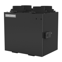
Exhaust and Supply in the Return
When using this installaon, make sure that there is
minimum of 3 feet (0.9m) between the fresh air
and exhaust air connecons of the HRV/ERV in
the return air duct. See Figure 3. Make sure
when using this installaon that the fresh air duct
connecon to the forced-air system return air
duct is not less than 10 (3 m) upstream of the
return plenum connecon to the forced air system.
Check with your local code or the forced air system's
manufacturer. The HRV and forced-air system must be
set to operate in connuous mode to achieve maximum
comfort and to avoid cross-contaminaon.
Note to installer: Dwellings with mulple forced-air
systems require one HRV/ERV per system.
Ensure the unit runs in conjuncon with forced-air system.
Refer to wiring diagram for furnace interlock instrucons.
Figure 3
* For minimum distance between return and forced-air system, check with
your local building codes or the manufacturer of the forced-air system.
Simplied Connection
2"
(51 cm)
Indirect Connection Breather Tee
Important: The duct bringing outdoor air to the return air
plenum must be equipped with a manual damper to balance the
outdoor airow.
Important: Building and combus-
on appliance installaon codes
do not allow return air grilles or
openings such as "breather tee" or
indirect connecons in an enclosed
room that is suscepble to spillage of
combuson appliances.
performing duct connecons, always use approved tools
and materials. Also use steel duct connecons for this
type of installaon.
Finding a Suitable Installation Location
The HRV/ERV unit should be installed in a mechanical room
or as close to an outside wall as possible. This would ensure
a short run of insulated exible duct.
The HRV/ERV unit must always be installed in an area where
the air is tempered to avoid freezing of the condensate
line. The contractor should install the unit in an area that
is accessible to allow the homeowner easy access for for
performing maintenance.
It is very important to install an electric receptacle (120VAC)
near the HRV/ERV. A separate circuit breaker is also recom-
mended. Installing the HRV/ERV close to a drain for the
condensate would avoid the need for a condensate pump.
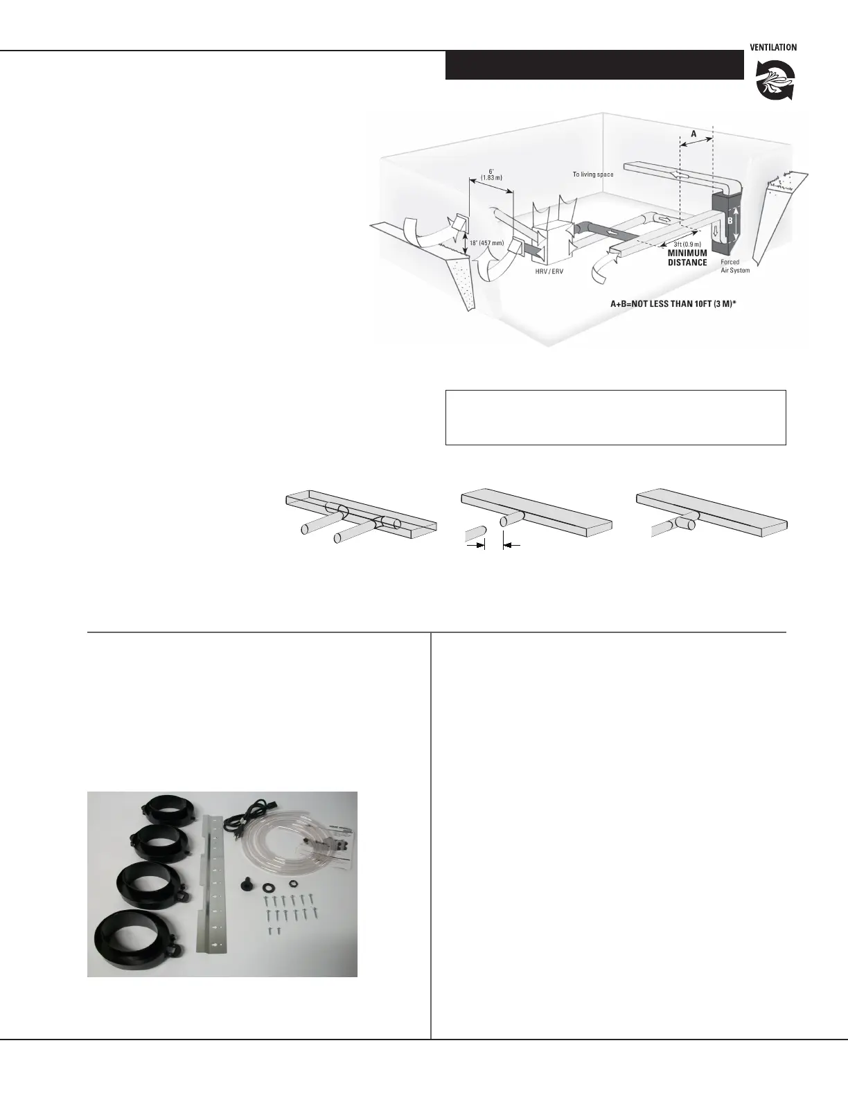
• 4 Collars
• 4 Caps, Pressure Taps
• 1 Condensaon Drain Line
• 1 Drain Adapter with Nut
• 12 screws (#10 x 11/4”)
• 2 screws (#8 x 3/8”)
• 120VAC power cord
• Wall-Mounng Bracket
Figure 4
Tip to Installer:
Removing the core unit will facilitate
your installaon.
Installation Kit
Installation Kit Includes: