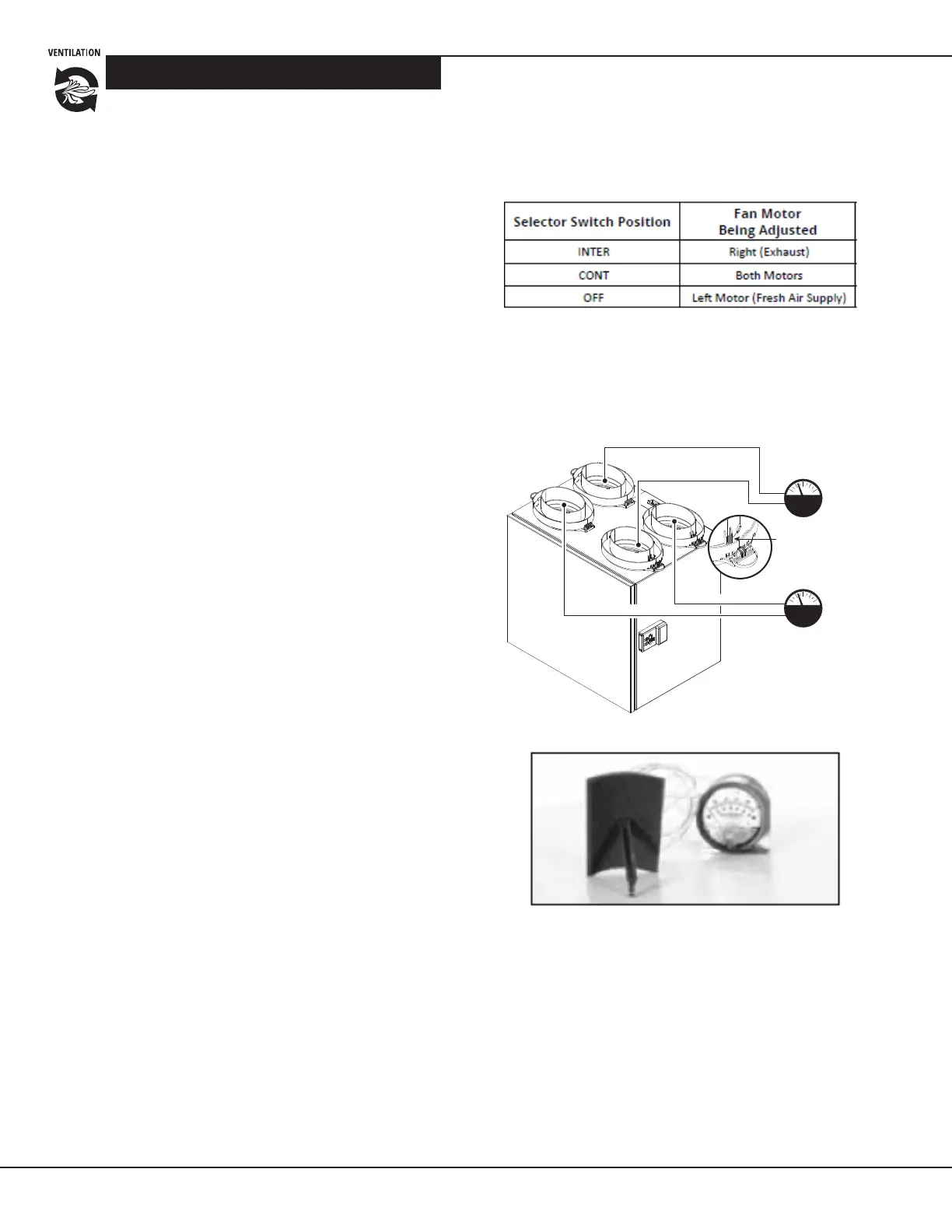
HIGH (Exhaust Air to Outside)
LOW (Exhaust Air from Home)
LOW (Fresh Air from Outside)
HIGH (Fresh Air to home)
HIGH (Exhaust Air to Outside)
LOW (Exhaust Air from Home)
Magnehelic gauge
Magnehelic gauge
Balancing Tap Connection
*
LOW (Fresh Air from Outside)
HIGH (Fresh Air to home)
SEQUENCE OF OPERATIONS
WWW.CLEANCOMFORT.COM
14
IO-VENT-SS
(+) and (–) buttons: These buons are used for adjusng
both the high and CONT fan speed sengs when the
control is in RUN mode.
BALANCING Mode
When the control is set to Balancing mode, the LED
indicator turns yellow and the selector switch is used for
seng the high speed of the fans for balancing purposes
(Supply (fresh) air, Exhaust air, and Both). The opons are:
• INTER (Intermittent): With the selector switch in this
posion, the speed of the exhaust air fan can be set
• CONT (Continuous): With the selector switch in this
posion, the speed of BOTH the exhaust and supply air
fans can be set
• OFF: With the selector switch in this posion, the speed
of the supply air fan can be set.
(+) and (–) buttons: These buons are used for adjusng
the fan speed of either or both of the supply and exhaust
fan motors, depending on the fan motor selected by the
posion of the selector switch. The + buon increases the
speed of the fan being adjusted
and the (– ) buon decreases the speed.
NOTES:
1. Connuous low speed is 50% of the fan speed
selected for HIGH speed.
2. When the LED stops ashing, the venlator is at
its maximum speed.
Procedure for Setting High (Override)
Airow Rate and Balancing the Ventilator
To balance the venlator, you will need to independently
adjust the ow rate in both the fresh air (supply) duct as
well as the stale air (exhaust) duct. You will need an airow
measuring device such as a pitot tube or a Magnehelic gauge.
NOTE: Turn the HVAC equipment fan ON while
performing these balancing steps
1. Once the total CFM needed is determined (see
Venlaon Requirements secon), you can start
balancing the HRV/ERV.
2. Set the three-posion selector switch on the venlator
control to either the INTER or CONT posion.
3. Press and hold both the (+) and (–) buons
simultaneously for 5 seconds unl the LED light turns
yellow, indicang the unit is now in Balancing mode.
4. When in Balancing mode, the selector switch becomes
the motor selector switch. The switch posion selects
which fan motors will be adjusted during balancing.
5. Adjust the airow rate in the fresh air duct by seng
the selector switch to the OFF posion.
6. Connect the airow measuring device to the integral
balancing taps on the venlator's collars.
Magnehelic Gauge with Airow Grid
7. Press the (+) and (–) buons on the venlator control
to increase or decrease the fan motor speed to pro-
duce the desired airow in the duct being measured.
Note: When the LED stops ashing, the venlator is
at its maximum speed.
Figure 12 Locaon
of balancing taps on
collars