BALANCING THE UNIT
WWW.CLEANCOMFORT.COM
15
IO-VENT-SS
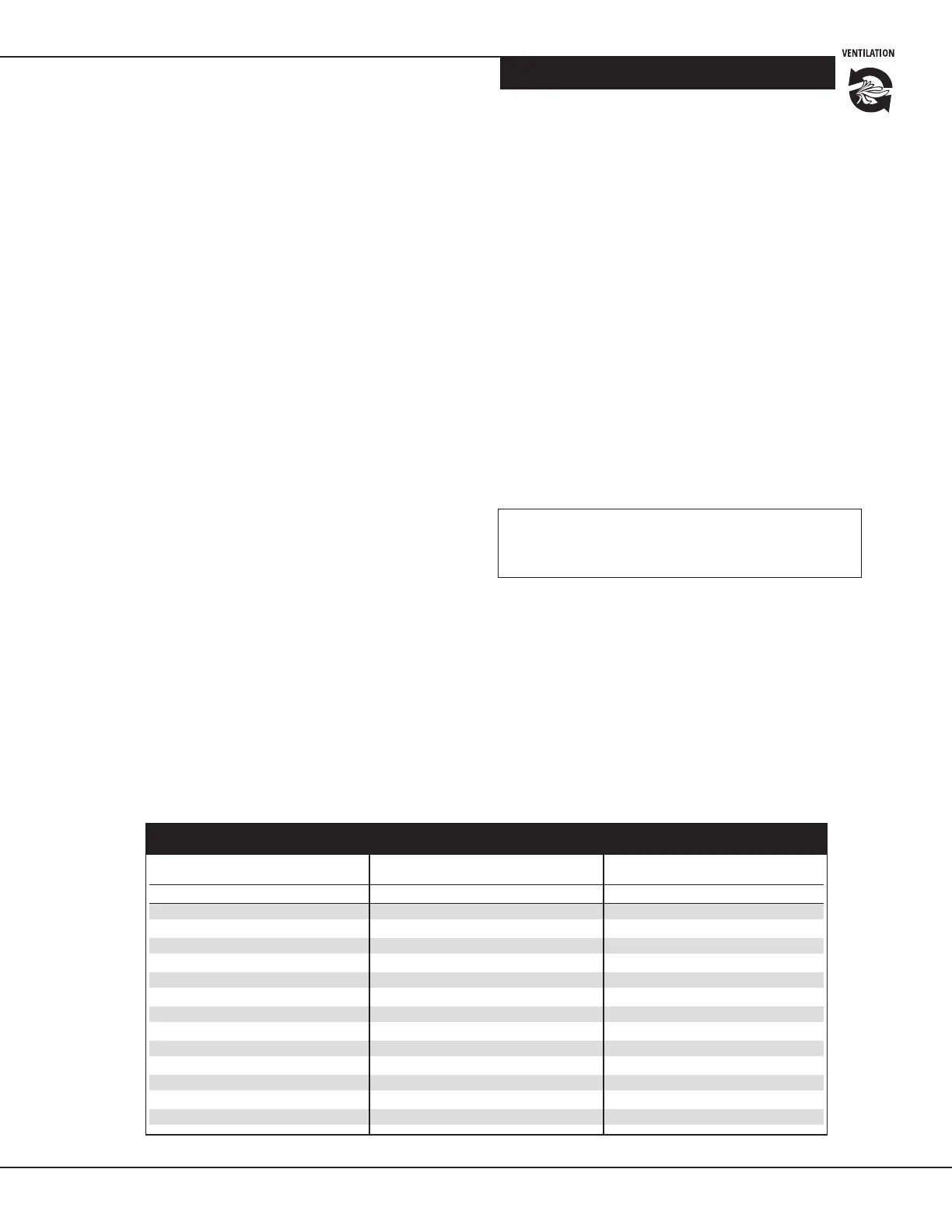
Balancing chart
This balancing chart is based on a Delta P (DP) reading from the
airow measuring device. A copy of this chart is also located on
the access panel of the venlator.
Note: To perform a proper installaon, the External Stac
Pressure (ESP) needs to be measured at each of the 4 staons.
Proceed to measure the Delta P (DP) to determine the cor-
responding airow (e.g. 50 CFM), then repeat unl the unit is
balanced for both the ESP and airows.
*Important: Once balancing is complete, ensure all four
pressure taps are sealed with the rubber caps. Pressure taps
are supplied in the installaon kit.
Pa in. wg L/s CFM L/s CFM
50 0.20 44 93 43 90
62 0.25 41 87 40 85
75 0.30 39 83 37 79
87 0.35 37 79 36 77
100 0.40 35 74 36 76
112 0.45 33 69 34 71
125 0.50 30 65 32 67
137 0.55 29 61 28 60
150 0.60 26 56 24 51
162 0.65 24 50 22 47
175 0.70 22 46 19 41
187 0.75 19 41 17 36
199 0.80 17 36 15 31
Balancing Chart when using collar pressure taps.
Pressure Fresh Air Exhaust Air
8. Perform the same operaon on the stale air side by
selecng the INTER posion on the selector switch.
Adjust the airow rate in the stale air duct to be the
same as the airow rate in the fresh air duct, so the
airow entering and leaving the building is balanced.
9. If necessary, the selector switch can be set to the CONT
posion, which will adjust the speed of both fan motors
at the same me.
10. Once this is done, you have set and locked the high
speed on your venlator and balanced the fresh and
stale airow rates.
11. To exit Balancing mode, press the (+) and (–) buons at
the same me unl the LED turns green, indicang that
the control has returned to Run mode.
Procedure for Setting Low
(Continuous) Ventilation Rate
When the unit is in Run mode, the connuous airow rate
can then be set by using the (+) and (–) buons and reading
the CFM using the airow measuring device.
1. When the unit is in Run mode, the connuous
airow rate can then be set by using the (+) and (–)
buons and reading the CFM using the airow
measuring device.
2. When the selector switch is set to the CONT posion,
the venlator runs at the low (connuous) speed unl
there’s a remote call for venlaon (override) from an
external control such as the VHP Series of controls.
Balancing Reset
Balancing of the venlator is locked upon exing Balancing
Mode and can only be changed with a reset of the control.
To Reset Control
1. Press the (+) and (–) buons simultaneously for 10
seconds. Aer 5 seconds, the LED will turn yellow and
aer 10 seconds, it will turn green
2. Release both buons
3. Unit has now been reset and is ready for re-
balancing, if necessary
Testing the Ventilator to Conrm Operation
1. Apply power to the venlator. Set the selector
switch to the CONT posion. Verify that the unit
turns on and operates at connuous speed
2. Turn the wall control to minimum humidity seng to
create a call for venlaon. Verify that the venlator
turns on and operates at high speed. Return wall
control to normal humidity seng.
3. Repeat for mer control, if one is installed
4. Return the selector switch to the desired posion
(INTER or CONT) and the wall control to the desired
sengs
5. Inspect the ductwork to verify there are no bends,
kinks or obstrucons to airow. Correct as needed.