INSTALLATION
WWW.CLEANCOMFORT.COM
9
IO-VENT-SS
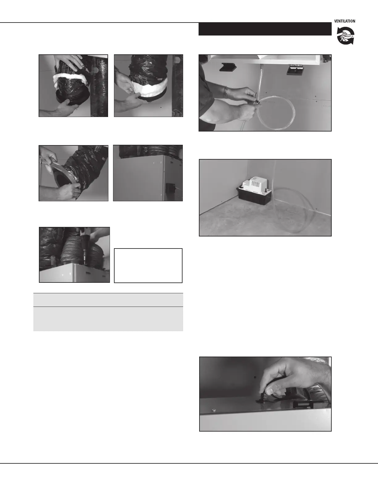
Condensation Drain Line
Insert the threaded drain adapter through the boom of the
HRV/ERV and hand ghten the plasc nut supplied with the
installaon kit. Use a wrench to ghten the nut another half turn
to ensure a complete seal.
Install the condensate line (included in installaon kit) by
pushing the clear plasc tubing over the drain adapter. Make
a condensate trap by looping the clear plasc tubing. The
funcon of this condensate trap is to prevent unpleasant odors
from entering the HRV/ERV. See Figures 14-15.
Figure 16
Insert the power cord on top of the unit.
Press rmly to make sure the power cord is secure.
Figure 14
Create a trap by forming a loop in the condensate tubing.
Ensure this trap will not be exposed to temperatures where the
condensate can freeze.
Supplying Power to the HRV/ERV
IMPORTANT: Only qualied service technicians should
install, repair, or service this HRV/ERV.
NOTE: If the LED light on the unit's control is lit (green),
but the unit's motors do not energize and the controls do
not operate, this indicates that the polarizaon in the main
power supply outlet is inverted. Correct polarity of supplied
power before connuing with the installaon.
Daikin recommends that the unit be connected to a dedi-
cated 120VAC receptacle; use of an extension cord to power
the unit is not recommended. If no receptacle is available
near the unit, have a licensed electrician install one.
Figure 15
Use a condensate pump if you don’t have access to a drain.
Figure 9 Insert exible duct
over the hooks and seal with a
tie wrap.
Figure 13
Fix and secure the collars
to the HRV/ERV with the #10 x 1
1
⁄4"
screws, supplied in kit.
Figure 11 Finish by taping the
vapor barrier to the collar to
ensure proper seal.
Figure 12 Slide collar into the
keeper section of the unit.
Figure 10 Insert insulaon inside
the double collar.
i WARNING!
Always secure the 5" detachable collars with the screws
provided. If this is not done, condensate may accumulate
inside the venlator causing damage.
CAUTION! Always consult
your naonal and local
regulaons, building and
safety codes.