INSTALLATION
WWW.CLEANCOMFORT.COM
8
IO-VENT-SS
Installation of the HRV/ERV
IMPORTANT Minimum installaon requirements:
a) Minimum two 2"x 4" (50.8 mm x 101.6 mm) wood
wall studs and minimum ⅜" (9.5 mm) thick drywall is
required to secure the HRV/ERV wall bracket.
b) Support for weight of 80 lbs, which includes HRV/
ERV, duct connecons and accessories. Proper instal-
laon requires that the unit be secured to the wall. If
there are no wall studs available, secure a sheet of ¾"
plywood to wall then fasten wall mounng bracket
to plywood.
Tip to installer: If the unit is not level, improper
drainage will occur and could lead to moisture and
leakage problems.
It is recommended that approximately 16 inches of exible
duct be installed between the HRV or ERV and your rigid
duct. The exible duct is connected to the HRV or ERV in
the same way as the insulated ex.
Insulated Flex from Unit to Outside Wall
Tip to installer: To ensure a beer installaon and to
avoid an undesired bend in the duct, align the exible duct
with the collar before securing over the four hooks on the
inner surfaces of the collar.
All ducng to and from the HRV/ERV must be adequately
insulated to minimize heat loss and gain. All tapes,
mascs, and nonmetallic clamps used for eld installaon
of exible ducts shall be listed and labeled to Standard UL
181B - Closure Systems for Use With Flexible Air Ducts and
Air Connectors.
Once insulated ex is aached to the collar, slide collar into
the keeper secon and aach collar to the unit with four,
#10 x 5/8" screws supplied in installaon kit to ensure a
proper seal. See Figures 9-13 on following page.
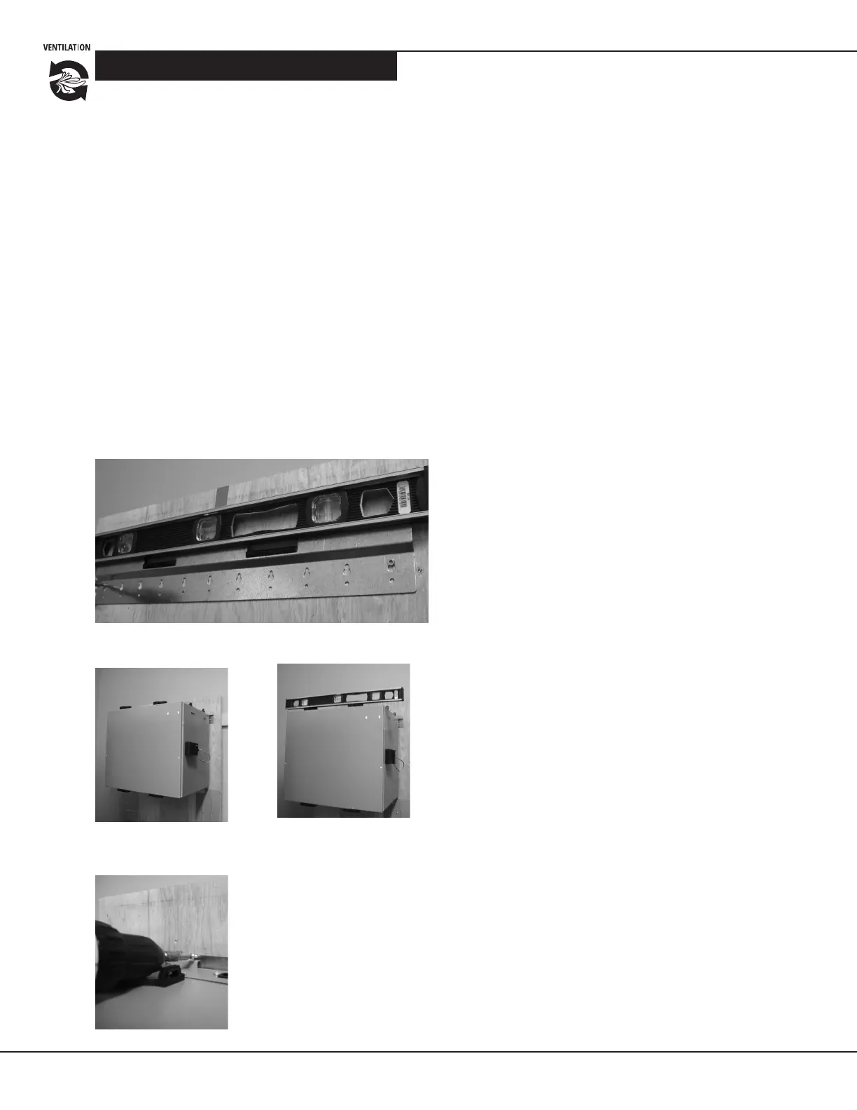
Figure
5
Installaon of the wall bracket. Secure with two
#10 x 1
1
⁄4" screws.
Figure 6 Hang HRV/ERV on
the wall-mounng bracket.
Figure 7 Before compleng
the installaon, make sure
that the HRV/ERV is level.
Figure 8 Secure HRV/ERV to
wall-mounng bracket with
the two, #8 x 3⁄8" screws.
NOTE: Clean Comfort Venlators (HRV/ERV) that use a
fan shut down defrost sequence for frost protecon are
NOT equipped with a motorized outdoor air damper.
Special consideraon is required when one of the follow-
ing types of installaons is chosen:
a) Exhaust at the source and supply in the return air duct,
or
b) Exhaust and supply in the return air duct
The HRV/ERV must operate in the connuous venlaon
mode to avoid cold, uncondioned air being introduced
through the unit and directly into the furnace during
heang season. However if the homeowner chooses to
run the unit in Intermient (“INTER”) mode or turn it
“OFF”, cold supply air will be drawn in through the HRV/
ERV when the system’s blower fan is operang e.g. during
a heang cycle. We recommend installing a motorized
damper between the HRV/ERV supply air connecon
and the furnace’s return air duct that will automacally
close when the HRV/ERV is not operang. You may also
consider the installaon of a backdra damper on the
venlator’s exhaust air connecon to prevent cold air
inltraon.
Alternavely, installing a venlator that employs a
recirculang defrost sequence and is equipped with
an integrated motorized outdoor air damper, such as
the VH30120R or VH30160R, would avoid the problem
described above.