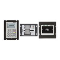
This document serves as an external user manual for the Verifone UX Suite of payment devices, specifically the UX 301 (card reader), UX 100 (PIN pad), and UX 401 (contactless reader). It provides comprehensive information for setting up, installing, and understanding the screen messages displayed during transaction processing when these devices are used in conjunction with the PAYWare Ocius Gateway.
The manual begins with a revision history, detailing updates made to the document. Version 1.0, dated September 6, 2017, marked the first release. Version 1.1, from June 19, 2017, removed internal references. The most recent update, Version 1.2 on July 24, 2017, included updates regarding terminal numbers and power supply.
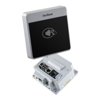
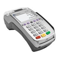
The "Get to Know the UX Suite of Devices" section offers a detailed overview of each component. The UX 301, the card reader, features mounting stud holes, status lights, an anti-removal switch, and a card slot on its front. The rear of the UX 301 includes a UX401 Power Port (A), a UX401 Antenna Port (B), a UX100 Port (C), a Power Port (D), an Ethernet Port (E), and a System Mode Access point. These ports facilitate the interconnection of the various devices within the UX suite.
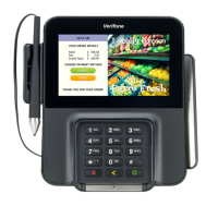
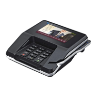
The UX 100, the PIN pad, presents a cardholder display, a keypad, and anti-removal switches on its front. The keypad includes numerical keys (0-9), as well as "STOP," "CORR," "INFO," and "OK" buttons, allowing for user interaction during transactions. The rear of the UX 100 features a USB Connector Port (C) and displays the terminal serial number.
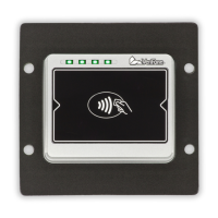
The UX 401, the contactless reader, has LED indicators and a contactless reader area on its front, along with mounting stud holes. The rear of the UX 401 includes a Power Port (A), an Antenna Port (B), and also displays the terminal serial number.
Installation instructions are provided to guide users through connecting the various components. The RJ45 Power Cable connects the UX301 to the UX401 via port A. The Antenna Cable links the UX301 to the UX401 through port B. The USB Data/Power Cable connects the UX301 to the UX100 via port C. A separate power cable is supplied for the UX301, connecting to port D. An Ethernet cable, not supplied by Verifone, connects to port E on the UX301 for network connectivity.
The manual also details the LED indicators for both the UX 301 and UX 401, providing visual cues for device status. For the UX 301, a solid red and green light indicates a card read. A solid orange light signifies system mode. A solid green light means the application has started. A solid red, green, and orange light indicates the terminal is rebooting. For the UX 401, one slow blinking light means the terminal is ready, while four solid lights indicate card processing.
Environmental factors are outlined to ensure optimal device performance. The UX 401 and UX 301 are designed to operate within a temperature range of -30°C to 70°C (-22°F to 158°F) and a storage temperature range of -30°C to 70°C (-22°F to 158°F), with 10% to 90% relative humidity (non-condensing). The UX 401 is IP65 rated, and the UX 301 is IP34 rated. The UX 100 operates within -20°C to 70°C (-4°F to 158°F) and stores within -25°C to 70°C (-13°F to 158°F), also with 10% to 90% relative humidity (non-condensing), and is IP65 and IK09 rated. The UX301 is the only device requiring a direct connection to the mains power supply, providing 12V DC 3.3A. Both the UX100 and UX401 draw power from the UX301.
The manual includes instructions on how to insert a card into the UX 301, emphasizing proper orientation with contacts facing upwards and firm insertion until seated. It also explains how to process a contactless card using the UX 401, by presenting the card within 4cm of the device until it beeps.
A crucial maintenance feature is the process for resetting anti-removal switches. Both the UX301 and UX100 are equipped with two such switches. These switches need to be reset during initial setup and anytime they are triggered during operation. The process involves plugging in the device, accessing the System Access Mode from the Ready Screen, pressing Enter, and then entering passwords for Switch1 and Switch2. The default passwords can be obtained from the appropriate team. A "Reset succeeded!" message confirms a successful reset. If the switches cannot be reset, an error message will be displayed. After resetting, the terminal returns to the login screen, where the user selects "Exit" and then "Reboot" to complete the process.
Connecting the device to a network is detailed in the "How to Connect Your Device" section, specifically for Ethernet connections, covering both DHCP and static IP configurations. This involves navigating through the device's menu options. From the Ready Screen, the user presses the System Access Mode button, selects "Supervisor," enters the Supervisor PIN, and then selects "Administration." From there, the user navigates to "Network" and then "Ethernet." The user must ensure "Enabled" is set to "on." If it's "off," they select "Enabled" and press the Up Arrow to activate it on boot. For static IPs, the user disables DHCP, then enters the required IP address, NETMASK address, and gateway address. After saving these settings, the user exits the menu and reboots the terminal.
The "Transaction Processing" section describes the on-screen messages displayed during a sale transaction. The terminal first shows "Ready," indicating it's awaiting instructions from the POS. The user then presents or inserts the payment card. If a card is inserted, the terminal prompts for the PIN. Next, the terminal displays "Connecting 1/3 Please Wait" as it connects to the Verifone PAYWare Ocius Gateway. During authorization, it shows "Authorising Please Wait." Upon successful approval, "Approved Transaction Approved!" is displayed, and the cardholder can remove their card. Finally, the terminal indicates "Printing Please wait Receipt is printing" as the cardholder's receipt is printed by the POS, before returning to the "Ready" screen, awaiting the next instruction. The messaging may vary depending on account settings and POS integration.
The manual concludes with contact details for Verifone Services UK & Ireland, including addresses, and contact information for the PAYWare Ocius Merchant Helpdesk, Technical Services, Customer Services, and Sales Enquiries, along with their respective operating hours. This comprehensive guide ensures users have the necessary information for effective operation and maintenance of their Verifone UX Suite devices.