To Table of Content
Controls and connectors
Front Panel/User Interface
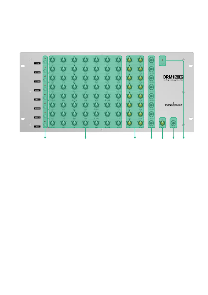
Figure 1:
User Interface of the DRM1 MKIV
q
TRIG button with LED – res off sound individually per instrument channel
w
Sound-shaping parameters (see “The Instrument Channels of the DRM1 MKIV”
on page 11)
e
PAN and VOLUME - channel volume and panning (see “Sound Generation” on
page 10)
r
OUT/INSERT - individual outputs/inserts (see “Individual Outputs/Inserts” on
page 21)
t
MASTER - overall volume
y
PHONES - headphones output
u
POWER LED - lights up when the DRM1 MKIV is powered up.
User Manual DRM1 MKIV8