8
Alignment
The alignment tool outline
Installation of the Alignment tool
The “alignment mode” is a software-based protocol, ac-
cessed by an “Alignment Mode” command from the com-
puter while switching the transceiver on. It is operated by
the alignment tool automatically. During use of the align-
ment mode, normal operation is suspended. The align-
ment tool program provides all needed operation capa-
bility.
Entering Alignment Mode
To enter the alignment mode, turn the transceiver off, ex-
ecute the CE53 programming software with the "/M" op-
tion (type "CE53 /M [ENTER]) and type the password
(please inquire the passward to Vertex Sandard). Select
“Radio” then “Alignment” parameter. Now, turn the
transceiver back on. When the command has been suc-
cessful, a message on the computer screen will confirm
that the transceiver is now in the “Alignment” mode.
Alignment Sequence
Although the data displayed on the computer's screen
during alignment is temporary data, it is important you
follow the basic alignment sequence precisely, so that the
displayed data and the data loaded into the transceiver
are identical.
Basic Alignment Sequence
1. Enter the alignment mode
2. Upload data from transceiver
3. Align data
4. Download data to transceiver
The transceiver must be programmed for use in the in-
tended system before alignment is attempted. The RF pa-
rameters are loaded from the file during the alignment
process.
In order to facilitate alignment over the complete operat-
ing rang of the equipment, it is recommended that the
channel data in the transceiver be preset as per the chart
below.
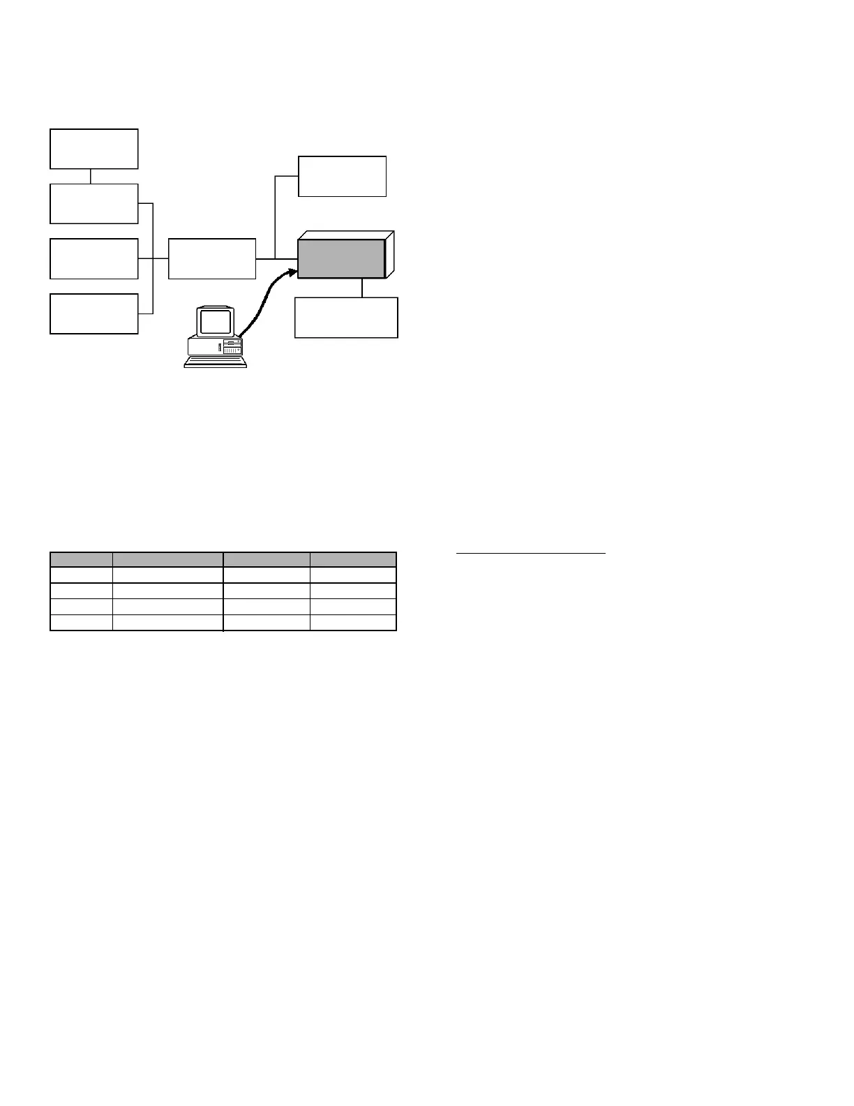
Set up the test equipment as shown below for transceiver
alignment, and apply 7.5V DC power to the transceiver.
50-ohm
Dummy Load
Inline Wattmeter
Deviation Meter
Frequency
Counter
RF Sampling
Coupler
RF Signal
Generator
Transceiver
Power Supply
7.5V DC
CT-42 connection
Cable
PC
MIC/EAR
COM port
Channel
1
2
3
4
Frequency
446.00625 MHz
446.05625 MHz
446.05625 MHz
446.09375 MHz
CTCSS Tone
–
67.0 Hz
103.5 Hz
–
DCS Code
–
627
627
–
 Loading...