9
PLL VCV (Varactor Control Voltage)
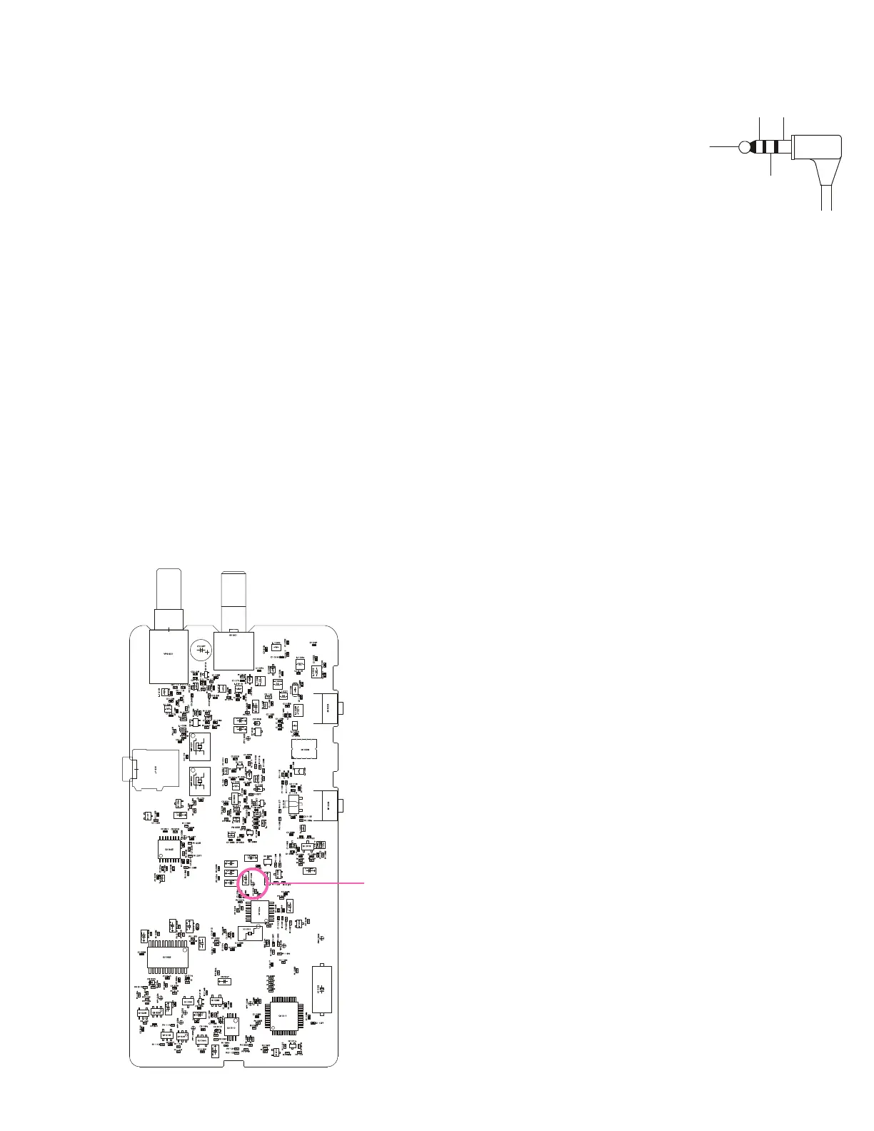
r Connect the DC voltmeter between TP1003 on the
Main Unit and ground.
r Set the transceiver to CH 4 via the “CH” box located
on the upper left corner on the “Alignment” window,
confirm that the voltage is more than 0.9 - 3.5V.
PLL Reference Frequency
r Set the transceiver to CH 2 via the “CH” box located
on the upper left corner on the “Alignment” window
previously.
r To adjustment, double-click the left mouse button on the “RF
Frequency” box to open the pop-up window, then move the
slide bar to adjust the frequency counter displays the
446.05625 MHz ± 100 Hz.
Transmitter Output Power
r Set the transceiver to CH 2 via the “CH” box located
on the upper left corner on the “Alignment” window
previously.
r To adjustment, double-click the left mouse button on the “RF
Power” box to open the pop-up window, then move the slide
bar to adjust the 0.5 W ± 0.1 W. Confirm that the current
consumption is 1.0 A or lower.
r Press the “OK” box to lock in the new data.
SP
CLONE GND
IN
Alignment
STD Deviation
r Inject a 1 kHz tone at –37
dBm to the MIC jack.
r To adjustment, double-click the
left mouse button on the “MIC
Sensitivity” box to open the
pop-up window, then move the
slide bar to adjust the ±1.5 kHz (±0.1 kHz) deviation.
r Press the “OK” box to lock in the new data.
MAX Deviation
r Set the transceiver to CH 2 via the “CH” box located
on the upper left corner on the “Alignment” window
previously.
r Inject a 1 kHz tone at –17 dBm to the MIC jack.
r To adjustment, double-click the left mouse button on the
“MAX Deviation” box to open the pop-up window, then move
the slide bar to adjust the ±2.1 kHz (±0.1 kHz) deviation.
r Press the “OK” box to lock in the new data.
CTCSS Deviation
r Set the transceiver to CH 3 via the “CH” box located
on the upper left corner on the “Alignment” window
previously.
r Double-click the left mouse button on the “CTCSS Balance”
box to open the pop-up window, then move the slide bar to
"00."
r To adjustment, double-click the left mouse button on the
“CTCSS Deviation” box to open the pop-up window, then
move the slide bar to adjust the ±1.0 kHz (±0.1 kHz) de-
viation.
r Press the “OK” box to lock in the new data.
r Set the transceiver to CH 2 via the “CH” box located
on the upper left corner on the “Alignment” window
previously.
r To adjustment, double-click the left mouse button on the
“CTCSS Balance” box to open the pop-up window, then
move the slide bar to "225." Move down the slide bar to
adjust the ±0.55 kHz (±0.1 kHz) deviation.
r Press the “OK” box to lock in the new data.
r Set the transceiver to CH 3, then key the transmitter,
and confirm that the deviation is 0.4 ~ 0.6 kHz.
DCS Deviation
r Set the transceiver to CH 2 via the “CH” box located
on the upper left corner on the “Alignment” window
previously.
r To adjustment, double-click the left mouse button on the
“DCS Deviation” box to open the pop-up window, then move
the slide bar to adjust the ±0.4 kHz (±0.05 kHz) deviation.
r Press the “OK” box to lock in the new data.
This completes the internal alignment routine. To save all
settings and exit, press the “OK” box.
TP1003
 Loading...