17
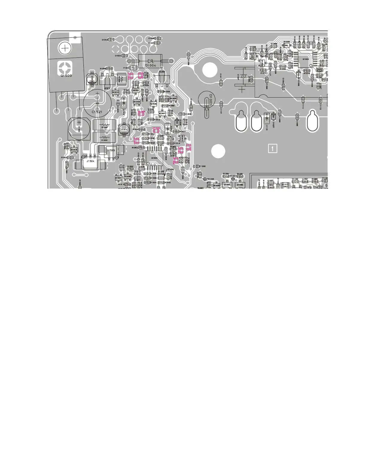
RF Unit Jumper Information
JP1501 (JP1): Determine the output supply voltage at pin 8 of DSUB 9-pin Accessory Connector.
Close: +5.0 V (Maximum 100 mA)
Open: No Action
JP1502 (JP2): Determine the output supply voltage at pin 8 of DSUB 9-pin Accessory Connector.
Close: +13.2 V (Maximum 100 mA)
Open: No Action
JP1503 (JP3): Determine the Rx discriminator output characteristic at pin 2 of DSUB 9-pin Accessory Connec-
tor.
Close: Flat 10 Hz to 3.0 kHz (140 mVrms / STD deviation with 600 ohm termination)
Open: No Action
JP1504 (JP4): Determine the Rx discriminator output characteristic at pin 2 of DSUB 9-pin Accessory Connec-
tor.
Close: Filtered 300 Hz to 3.0 kHz (70 mVrms / STD deviation with 600 ohm termination)
Open: No Action
JP1505 (JP5): No Action (Spare Jumper).
JP1506 (JP6): Define whether the TX Data Input at pin 3 of DSUB 9-pin Accessory Connector shall be "on" or
"off" according to the external PTT Input signal signal (pin 7 of DSUB 9-pin Accessory Connec-
tor).
Close: on (Enabled)
Open: off (Disabled)
JP1507 (JP7): Determine the TX Data Input level at pin 3 of DSUB 9-pin Accessory Connector.
Close: 400 mVrms / STD deviation with 600 ohm termination
Open: 40 mVrms / STD deviation with 600 ohm termination
JP1508 (JP8): Define whether the Transceiver's power shall be "on" or "off" according to the Ignition Signal
Input (pin 9 of DSUB 9-pin Accessory Connector).
Close: Turn the transceiver on when the Ignition Signal Input (pin 9 of DSUB 9-pin Accessory
Connector) is turned to "High" while the VOL/PWR knob is set to the "ON" position (out
of the click-stop position).
Open: No Action